Information injection-pump assembly
ZEXEL
106873-3031
1068733031
HINO
220007831A
220007831a

Rating:
Cross reference number
ZEXEL
106873-3031
1068733031
HINO
220007831A
220007831a
Zexel num
Bosch num
Firm num
Name
Calibration Data:
Adjustment conditions
Test oil
1404 Test oil ISO4113 or {SAEJ967d}
1404 Test oil ISO4113 or {SAEJ967d}
Test oil temperature
degC
40
40
45
Nozzle and nozzle holder
105780-8140
Bosch type code
EF8511/9A
Nozzle
105780-0000
Bosch type code
DN12SD12T
Nozzle holder
105780-2080
Bosch type code
EF8511/9
Opening pressure
MPa
17.2
Opening pressure
kgf/cm2
175
Injection pipe
Outer diameter - inner diameter - length (mm) mm 8-3-600
Outer diameter - inner diameter - length (mm) mm 8-3-600
Overflow valve
134424-0820
Overflow valve opening pressure
kPa
127
107
147
Overflow valve opening pressure
kgf/cm2
1.3
1.1
1.5
Tester oil delivery pressure
kPa
157
157
157
Tester oil delivery pressure
kgf/cm2
1.6
1.6
1.6
Direction of rotation (viewed from drive side)
Right R
Right R
Injection timing adjustment
Direction of rotation (viewed from drive side)
Right R
Right R
Injection order
1-8-6-2-
7-5-4-3
Pre-stroke
mm
4.5
4.44
4.5
Beginning of injection position
Drive side NO.1
Drive side NO.1
Difference between angles 1
Cal 1-8 deg. 45 44.75 45.25
Cal 1-8 deg. 45 44.75 45.25
Difference between angles 2
Cal 1-6 deg. 90 89.75 90.25
Cal 1-6 deg. 90 89.75 90.25
Difference between angles 3
Cyl.1-2 deg. 135 134.75 135.25
Cyl.1-2 deg. 135 134.75 135.25
Difference between angles 4
Cal 1-7 deg. 180 179.75 180.25
Cal 1-7 deg. 180 179.75 180.25
Difference between angles 5
Cal 1-5 deg. 225 224.75 225.25
Cal 1-5 deg. 225 224.75 225.25
Difference between angles 6
Cal 1-4 deg. 270 269.75 270.25
Cal 1-4 deg. 270 269.75 270.25
Difference between angles 7
Cal 1-3 deg. 315 314.75 315.25
Cal 1-3 deg. 315 314.75 315.25
Injection quantity adjustment
Adjusting point
A
Rack position
9.2
Pump speed
r/min
700
700
700
Average injection quantity
mm3/st.
157.6
155.6
159.6
Max. variation between cylinders
%
0
-2
2
Basic
*
Fixing the lever
*
Injection quantity adjustment_02
Adjusting point
B
Rack position
9.1
Pump speed
r/min
500
500
500
Average injection quantity
mm3/st.
160.7
157.7
163.7
Fixing the lever
*
Injection quantity adjustment_03
Adjusting point
D
Rack position
9.25+-0.
5
Pump speed
r/min
1100
1100
1100
Average injection quantity
mm3/st.
143.7
139.7
147.7
Fixing the lever
*
Injection quantity adjustment_04
Adjusting point
E
Rack position
8.5
Pump speed
r/min
1200
1200
1200
Average injection quantity
mm3/st.
129
126
132
Fixing the lever
*
Injection quantity adjustment_05
Adjusting point
F
Rack position
3.9+-0.5
Pump speed
r/min
225
225
225
Average injection quantity
mm3/st.
12.6
9.6
15.6
Max. variation between cylinders
%
0
-15
15
Fixing the rack
*
Injection quantity adjustment_06
Adjusting point
G
Rack position
9.85+-0.
1
Pump speed
r/min
300
300
300
Average injection quantity
mm3/st.
178.5
174.5
182.5
Fixing the lever
*
Remarks
Startup boost setting
Startup boost setting
Injection quantity adjustment_07
Adjusting point
H
Rack position
-
Pump speed
r/min
100
100
100
Average injection quantity
mm3/st.
188
188
208
Fixing the lever
*
Remarks
After startup boost setting
After startup boost setting
Timer adjustment
Pump speed
r/min
600--
Advance angle
deg.
0
0
0
Load
1/4
Remarks
Start
Start
Timer adjustment_02
Pump speed
r/min
550
Advance angle
deg.
0.3
Load
1/4
Timer adjustment_03
Pump speed
r/min
700--
Advance angle
deg.
1
0.7
1.3
Load
4/4
Timer adjustment_04
Pump speed
r/min
900+50
Advance angle
deg.
1
0.7
1.3
Load
3/4
Timer adjustment_05
Pump speed
r/min
1100-50
Advance angle
deg.
4.75
4.45
5.05
Load
4/4
Remarks
Finish
Finish
Test data Ex:
Governor adjustment
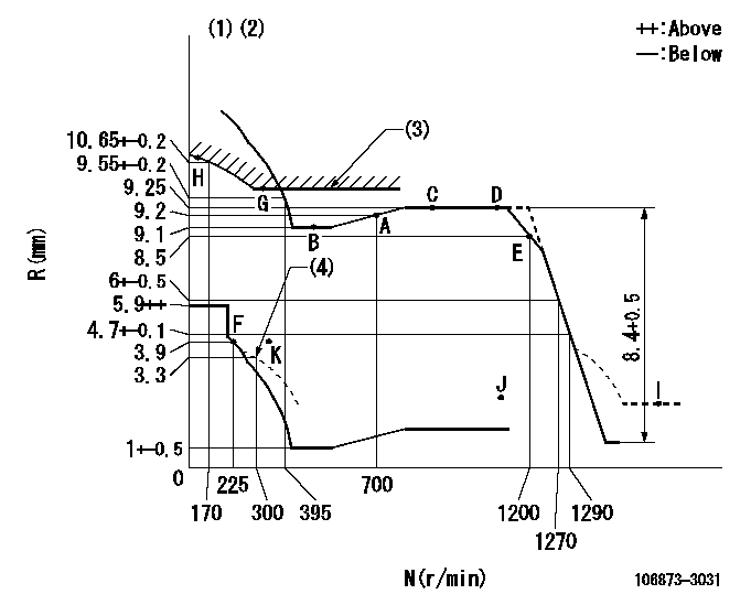
N:Pump speed
R:Rack position (mm)
(1)Tolerance for racks not indicated: +-0.05mm.
(2)Set idle at point K (N = N1, R = R1) and confirm that the injection quantity does not exceed Q1 at point J (N = N2).
(3)Excess fuel setting for starting: SXL
(4)Damper spring setting
----------
N1=300r/min R1=3.9mm N2=1150r/min Q1=3mm3/st SXL=9.85+-0.1mm
----------
----------
N1=300r/min R1=3.9mm N2=1150r/min Q1=3mm3/st SXL=9.85+-0.1mm
----------
Speed control lever angle

F:Full speed
----------
----------
a=15.5deg+-5deg
----------
----------
a=15.5deg+-5deg
0000000901

F:Full load
I:Idle
(1)Use the hole at R = aa
(2)Stopper bolt setting
----------
aa=39mm
----------
a=39deg+-5deg b=43.5deg+-3deg
----------
aa=39mm
----------
a=39deg+-5deg b=43.5deg+-3deg
Stop lever angle
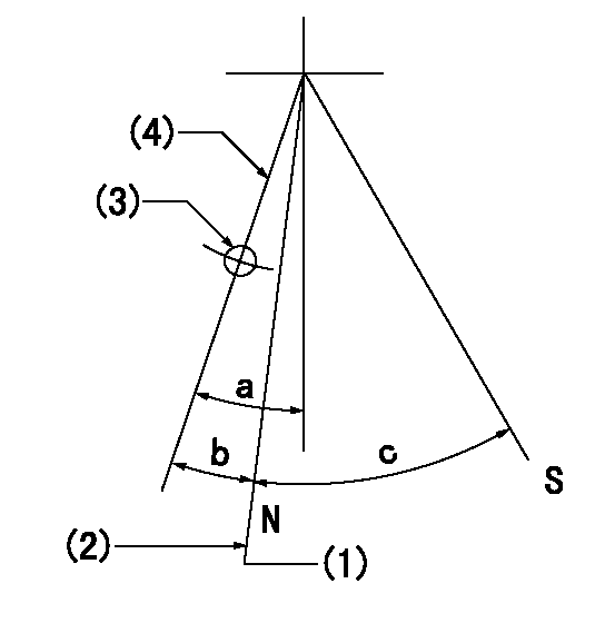
N:Pump normal
S:Stop the pump.
(1)Rack position = aa (at delivery), set before governor adjustment
(2)Set the stopper bolt (after setting apply red paint).
(3)Use the pin at R = bb
(4)Lever free
----------
aa=12+-0.1mm bb=37mm
----------
a=(9deg)+-5deg b=9deg+-5deg c=35deg+-5deg
----------
aa=12+-0.1mm bb=37mm
----------
a=(9deg)+-5deg b=9deg+-5deg c=35deg+-5deg
0000001501 RACK SENSOR

(VR) measurement voltage
(I) Part number of the control unit
(G) Apply red paint.
(H): End surface of the pump
1. Rack sensor adjustment (-0620)
(1)Fix the speed control lever at the full position
(2)Set the speed to N1 r/min.
(If the boost compensator is provided, apply boost pressure.)
(3)Adjust the bobbin (A) so that the rack sensor's output voltage is VR+-0.01.
(4)At that time, rack position must be Ra.
(5)Apply G at two places.
Connecting part between the joint (B) and the nut (F)
Connecting part between the joint (B) and the end surface of the pump (H)
----------
N1=1100r/min Ra=(9.25)mm
----------
----------
N1=1100r/min Ra=(9.25)mm
----------
Timing setting

(1)Pump vertical direction
(2)Coupling's key groove position at No 1 cylinder's beginning of injection
(3)-
(4)-
----------
----------
a=(80deg)
----------
----------
a=(80deg)
Information:
Operation-Jacobs Brake
The Jacobs Engine Brake should not be used as a primary or service brake.Do not allow the engine to exceed 2300 rpm. However, engines equipped with a Jacobs Engine Brake should not be operated above 2100 rpm.
The Jacobs Engine Brake is an engine attachment that converts a diesel engine into an air compressor. Its function is to slow the vehicle and reduce brake wear.Operating Controls-Jacobs Brake
The Jacobs Engine Brake controls may include a dash mounted module or an ON/OFF switch and a three position switch with "Lo," "Med" and "Hi" depending on how many cylinders of braking desired. Refer to your truck manufacturer's Owner Manual for the type of operating controls that your vehicle is equipped with.The 3176 ECM monitors the clutch, brake, throttle position and engine rpm to determine when the Jacobs Brake can operate. It may take up to two seconds before Jacobs Brake activates.Since the Jacobs Engine Brake is most effective at rated engine rpm, gear selection is very important. Gearing down the vehicle, within the limits of rated engine rpm, makes the engine brake a more effective retarder. Maximum retarding occurs at higher engine rpm.Cruise Control (If Equipped) OFF
With the Cruise Control (CC) in the OFF position the Jacobs Engine Brake will function like any vehicle and engine that is not equipped with Cruise Control (CC).Cruise Control (If Equipped) ON
The driver must apply the service brake approximately two seconds and then release the service brake pedal. If the retarder "Latch" mode has been programmed, the retarder will continue to slow the vehicle. To release order activate the retarder, the clutch or throttle foot pedal must be depressed or the engine rpm drop to 950 rpm.When using "Coast" mode, the Jacobs Brake should activate within two seconds after the brake pedal is applied and remain on as long as the brake pedal is applied. At the time the brake pedal is applied, the Cruise Control (CC) will deactivate.For information on adjustment to Jacobs Brake slave piston lash, refer to PM Level 2-Engine Valve Lash. Refer to Jacobs Brake Troubleshooting Manual, Form SENR4251 for information regarding this auxiliary braking system.