Information injection-pump assembly
BOSCH
F 019 Z10 277
f019z10277
ZEXEL
106873-2942
1068732942
Rating:
Service parts 106873-2942 INJECTION-PUMP ASSEMBLY:
1.
_
7.
COUPLING PLATE
8.
_
9.
_
11.
Nozzle and Holder
ME093732
12.
Open Pre:MPa(Kqf/cm2)
17.7{180}/21.6{220}
14.
NOZZLE
Include in #1:
106873-2942
as INJECTION-PUMP ASSEMBLY
Cross reference number
BOSCH
F 019 Z10 277
f019z10277
ZEXEL
106873-2942
1068732942
Zexel num
Bosch num
Firm num
Name
Calibration Data:
Adjustment conditions
Test oil
1404 Test oil ISO4113 or {SAEJ967d}
1404 Test oil ISO4113 or {SAEJ967d}
Test oil temperature
degC
40
40
45
Nozzle and nozzle holder
105780-8140
Bosch type code
EF8511/9A
Nozzle
105780-0000
Bosch type code
DN12SD12T
Nozzle holder
105780-2080
Bosch type code
EF8511/9
Opening pressure
MPa
17.2
Opening pressure
kgf/cm2
175
Injection pipe
Outer diameter - inner diameter - length (mm) mm 8-3-600
Outer diameter - inner diameter - length (mm) mm 8-3-600
Overflow valve
131425-0220
Overflow valve opening pressure
kPa
157
123
191
Overflow valve opening pressure
kgf/cm2
1.6
1.25
1.95
Tester oil delivery pressure
kPa
157
157
157
Tester oil delivery pressure
kgf/cm2
1.6
1.6
1.6
Direction of rotation (viewed from drive side)
Right R
Right R
Injection timing adjustment
Direction of rotation (viewed from drive side)
Right R
Right R
Injection order
1-2-7-3-
4-5-6-8
Pre-stroke
mm
3.9
3.85
3.95
Beginning of injection position
Governor side NO.1
Governor side NO.1
Difference between angles 1
Cyl.1-2 deg. 45 44.5 45.5
Cyl.1-2 deg. 45 44.5 45.5
Difference between angles 2
Cal 1-7 deg. 90 89.5 90.5
Cal 1-7 deg. 90 89.5 90.5
Difference between angles 3
Cal 1-3 deg. 135 134.5 135.5
Cal 1-3 deg. 135 134.5 135.5
Difference between angles 4
Cal 1-4 deg. 180 179.5 180.5
Cal 1-4 deg. 180 179.5 180.5
Difference between angles 5
Cal 1-5 deg. 225 224.5 225.5
Cal 1-5 deg. 225 224.5 225.5
Difference between angles 6
Cal 1-6 deg. 270 269.5 270.5
Cal 1-6 deg. 270 269.5 270.5
Difference between angles 7
Cal 1-8 deg. 315 314.5 315.5
Cal 1-8 deg. 315 314.5 315.5
Injection quantity adjustment
Adjusting point
-
Rack position
12.2
Pump speed
r/min
700
700
700
Each cylinder's injection qty
mm3/st.
109
105.7
112.3
Basic
*
Fixing the rack
*
Standard for adjustment of the maximum variation between cylinders
*
Injection quantity adjustment_02
Adjusting point
Z
Rack position
8.5+-0.5
Pump speed
r/min
510
510
510
Each cylinder's injection qty
mm3/st.
16
13.6
18.4
Fixing the rack
*
Standard for adjustment of the maximum variation between cylinders
*
Injection quantity adjustment_03
Adjusting point
A
Rack position
R1(12.2)
Pump speed
r/min
700
700
700
Average injection quantity
mm3/st.
109
108
110
Basic
*
Fixing the lever
*
Injection quantity adjustment_04
Adjusting point
B
Rack position
R1+1.15
Pump speed
r/min
1100
1100
1100
Average injection quantity
mm3/st.
118
114
122
Fixing the lever
*
Injection quantity adjustment_05
Adjusting point
C
Rack position
(R1-0.8)
Pump speed
r/min
500
500
500
Average injection quantity
mm3/st.
104
100
108
Fixing the lever
*
Test data Ex:
Governor adjustment

N:Pump speed
R:Rack position (mm)
(1)Torque cam stamping: T1
(2)Tolerance for racks not indicated: +-0.05mm.
(3)Damper spring setting
----------
T1=AB22
----------
----------
T1=AB22
----------
Timer adjustment

(1)Adjusting range
(2)Step response time
(N): Speed of the pump
(L): Load
(theta) Advance angle
(Srd1) Step response time 1
(Srd2) Step response time 2
1. Adjusting conditions for the variable timer
(1)Adjust the clearance between the pickup and the protrusion to L.
----------
L=1-0.2mm N2=800r/min C2=(10)deg t1=2.5--sec. t2=2.5--sec.
----------
N1=750++r/min P1=0kPa(0kgf/cm2) P2=392kPa(4kgf/cm2) C1=10+-0.3deg R01=0/4load R02=4/4load
----------
L=1-0.2mm N2=800r/min C2=(10)deg t1=2.5--sec. t2=2.5--sec.
----------
N1=750++r/min P1=0kPa(0kgf/cm2) P2=392kPa(4kgf/cm2) C1=10+-0.3deg R01=0/4load R02=4/4load
Speed control lever angle
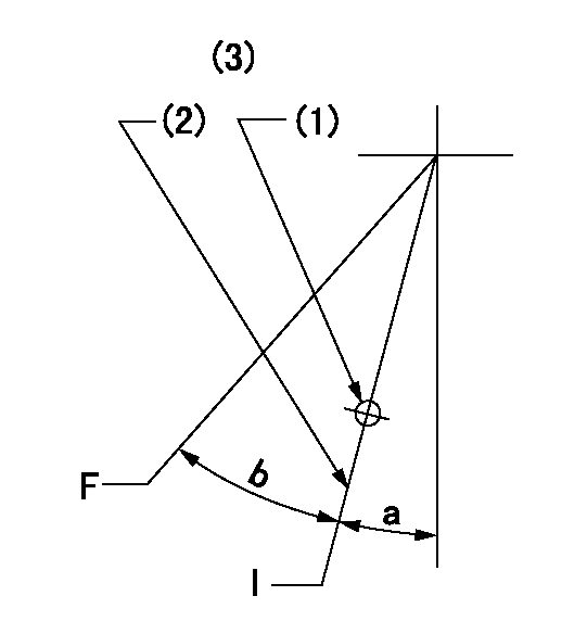
F:Full speed
I:Idle
(1)Use the hole at R = aa
(2)Stopper bolt set position 'H'
(3)Viewed from feed pump side.
----------
aa=37.5mm
----------
a=30deg+-5deg b=(44deg)+-3deg
----------
aa=37.5mm
----------
a=30deg+-5deg b=(44deg)+-3deg
Stop lever angle

N:Pump normal
S:Stop the pump.
(1)Use the hole at R = aa
(2)Set the stopper bolt so that speed = bb and rack position = cc. (Confirm non-injection.)
(3)Normal engine position (Rack position corresponding to dd)
----------
aa=31.5mm bb=1100r/min cc=3.5+-0.3mm dd=18mm
----------
a=(31deg)+-5deg b=11.5deg+-5deg c=41deg+-5deg
----------
aa=31.5mm bb=1100r/min cc=3.5+-0.3mm dd=18mm
----------
a=(31deg)+-5deg b=11.5deg+-5deg c=41deg+-5deg
0000001501 MICRO SWITCH
Adjustment of the micro-switch
Adjust the bolt to obtain the following lever position when the micro-switch is ON.
(1)Speed N1
(2)Rack position Ra
----------
N1=325r/min Ra=8.5+-0.1mm
----------
----------
N1=325r/min Ra=8.5+-0.1mm
----------
0000001601 RACK SENSOR

(VR) measurement voltage
(I) Part number of the control unit
(G) Apply red paint.
(H): End surface of the pump
1. Rack sensor adjustment (-0620)
(1)Fix the speed control lever at the full position
(2)Set the speed to N1 r/min.
(If the boost compensator is provided, apply boost pressure.)
(3)Adjust the bobbin (A) so that the rack sensor's output voltage is VR+-0.01.
(4)At that time, rack position must be Ra.
(5)Apply G at two places.
Connecting part between the joint (B) and the nut (F)
Connecting part between the joint (B) and the end surface of the pump (H)
----------
N1=1100r/min Ra=R1(12.2)+1.15mm
----------
----------
N1=1100r/min Ra=R1(12.2)+1.15mm
----------
Timing setting

(1)Pump vertical direction
(2)Coupling's key groove position at No 1 cylinder's beginning of injection
(3)B.T.D.C.: aa
(4)-
----------
aa=4deg
----------
a=(50deg)
----------
aa=4deg
----------
a=(50deg)
Information:
You must read and understand the warnings and instructions contained in the Safety section of this manual before performing any operation or maintenance procedures.For most users of 3406 Marine Engines, a top end overhaul is not needed until the major OVERHAUL interval of Every 10,000 Hours or fuel consumption interval for your engine.A top end overhaul is generally indicated by increased fuel consumption and reduced power. This option consists of completely reconditioning your cylinder head, but the cylinder components are not worn enough to need repair.Expected engine life (time to overhaul) can be expressed in terms of liters (gallons) of fuel consumed and can generally be predicted by the average power demanded of the engine over a period of time. Reduced hours of operation at full throttle and/or operating at reduced throttle settings result in lower average power demand and should increase the length of operating time before an engine overhaul is required. Other factors, such as how conscientiously preventive maintenance has been performed, fuel quality, operating conditions, S O S results, etc., are important in deciding when to perform an overhaul.Overhaul Programs
Your Caterpillar dealer may be offering a variety of options regarding overhaul programs and Caterpillar recommends that an Overhaul be performed at this maintenance interval.Overhaul Options
Caterpillar Dealer - Contact your Caterpillar dealer to schedule a Before Failure Overhaul. Overhaul Kit - This useful kit was developed for those users that prefer to perform their own overhaul. This kit includes a combination of new, reused and Remanufactured parts. Also included is a step-by-step instruction regarding how to perform an overhaul. An Overhaul Kit simplifies parts ordering, helps speed repairs and reduces parts costs.Contact your local Caterpillar dealer for information regarding the Overhaul Kit.Overhaul Recommendation
Overhaul programs vary from dealer to dealer. Therefore, Caterpillar recommends that you confer with your dealer to obtain specific information regarding the types of programs offered and overhaul services provided for extending the life of your engine.After Failure Overhaul
If you experience a major engine failure which requires removal of the engine, there are also many After Failure Overhaul options available. An overhaul should be performed if your block or crankshaft needs to be repaired.If the block and/or crankshaft is repairable, then the cost of an overhaul should be between 40 and 50 percent of the cost of a new engine (with like exchange core).This lower cost can be attributed to Caterpillar "designed-in" features that include regrindable crankshaft, undersize bearings, if needed and Cat dealer and Caterpillar Remanufactured exchange components.The following is a list of (R) Remanufactured components that can be found in the Parts Manual and currently being offered by Caterpillar* in many countries:* Short block* Cylinder pack1* Cylinder head - bare casting* Cylinder head - assembled* Crankshaft - undersized*** Crankshaft - upgrade to new* Complete turbocharger* Turbocharger Piece Parts* Turbocharger Cartridges* Water pump* Oil pump* Fuel injectors (when applicable)* Alternator* Starting motor If the component you need is not listed here, contact your Caterpillar dealer to see if it is offered under