Information injection-pump assembly
BOSCH
9 400 618 397
9400618397
ZEXEL
106873-2890
1068732890
MITSUBISHI
ME160956
me160956
Rating:
Service parts 106873-2890 INJECTION-PUMP ASSEMBLY:
1.
_
7.
COUPLING PLATE
8.
_
9.
_
11.
Nozzle and Holder
ME160666
12.
Open Pre:MPa(Kqf/cm2)
17.7{180}/24.5{250}

15.
NOZZLE SET
Include in #1:
106873-2890
as INJECTION-PUMP ASSEMBLY
Cross reference number
BOSCH
9 400 618 397
9400618397
ZEXEL
106873-2890
1068732890
MITSUBISHI
ME160956
me160956
Zexel num
Bosch num
Firm num
Name
106873-2890
9 400 618 397
ME160956 MITSUBISHI
INJECTION-PUMP ASSEMBLY
8M20-2 K
8M20-2 K
Calibration Data:
Adjustment conditions
Test oil
1404 Test oil ISO4113 or {SAEJ967d}
1404 Test oil ISO4113 or {SAEJ967d}
Test oil temperature
degC
40
40
45
Nozzle and nozzle holder
105780-8140
Bosch type code
EF8511/9A
Nozzle
105780-0000
Bosch type code
DN12SD12T
Nozzle holder
105780-2080
Bosch type code
EF8511/9
Opening pressure
MPa
17.2
Opening pressure
kgf/cm2
175
Injection pipe
Outer diameter - inner diameter - length (mm) mm 8-3-600
Outer diameter - inner diameter - length (mm) mm 8-3-600
Overflow valve
131424-4620
Overflow valve opening pressure
kPa
255
221
289
Overflow valve opening pressure
kgf/cm2
2.6
2.25
2.95
Tester oil delivery pressure
kPa
157
157
157
Tester oil delivery pressure
kgf/cm2
1.6
1.6
1.6
Direction of rotation (viewed from drive side)
Right R
Right R
Injection timing adjustment
Direction of rotation (viewed from drive side)
Right R
Right R
Injection order
1-2-7-3-
4-5-6-8
Pre-stroke
mm
4.8
4.75
4.85
Beginning of injection position
Governor side NO.1
Governor side NO.1
Difference between angles 1
Cyl.1-2 deg. 45 44.5 45.5
Cyl.1-2 deg. 45 44.5 45.5
Difference between angles 2
Cal 1-7 deg. 90 89.5 90.5
Cal 1-7 deg. 90 89.5 90.5
Difference between angles 3
Cal 1-3 deg. 135 134.5 135.5
Cal 1-3 deg. 135 134.5 135.5
Difference between angles 4
Cal 1-4 deg. 180 179.5 180.5
Cal 1-4 deg. 180 179.5 180.5
Difference between angles 5
Cal 1-5 deg. 225 224.5 225.5
Cal 1-5 deg. 225 224.5 225.5
Difference between angles 6
Cal 1-6 deg. 270 269.5 270.5
Cal 1-6 deg. 270 269.5 270.5
Difference between angles 7
Cal 1-8 deg. 315 314.5 315.5
Cal 1-8 deg. 315 314.5 315.5
Injection quantity adjustment
Adjusting point
-
Rack position
10.4
Pump speed
r/min
650
650
650
Each cylinder's injection qty
mm3/st.
140
135.8
144.2
Basic
*
Fixing the rack
*
Standard for adjustment of the maximum variation between cylinders
*
Injection quantity adjustment_02
Adjusting point
C
Rack position
6.8+-0.5
Pump speed
r/min
225
225
225
Each cylinder's injection qty
mm3/st.
19
16.1
21.9
Fixing the rack
*
Standard for adjustment of the maximum variation between cylinders
*
Injection quantity adjustment_03
Adjusting point
A
Rack position
R1(10.4)
Pump speed
r/min
650
650
650
Average injection quantity
mm3/st.
140
139
141
Basic
*
Fixing the lever
*
Injection quantity adjustment_04
Adjusting point
E
Rack position
-
Pump speed
r/min
100
100
100
Average injection quantity
mm3/st.
165
125
205
Fixing the lever
*
Remarks
After startup boost setting
After startup boost setting
Timer adjustment
Pump speed
r/min
900--
Advance angle
deg.
0
0
0
Remarks
Start
Start
Timer adjustment_02
Pump speed
r/min
850
Advance angle
deg.
0.5
Timer adjustment_03
Pump speed
r/min
1100
Advance angle
deg.
4.5
4
5
Remarks
Finish
Finish
Test data Ex:
Governor adjustment
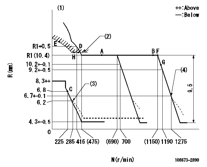
N:Pump speed
R:Rack position (mm)
(1)Tolerance for racks not indicated: +-0.05mm.
(2)Excess fuel setting for starting: SXL
(3)Damper spring setting
(4)When air cylinder is operating.
----------
SXL=10.6+-0.1mm
----------
----------
SXL=10.6+-0.1mm
----------
Speed control lever angle
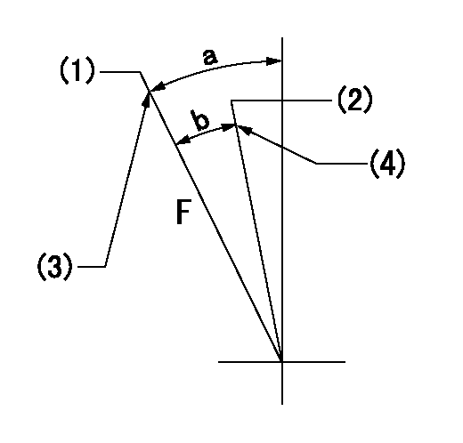
F:Full speed
(1)Set the pump speed at aa
(2)Set the pump speed at bb.
(3)Stopper bolt setting
(4)Stopper bolt setting
----------
aa=1275r/min bb=700r/min
----------
a=(22deg)+-5deg b=(5.5deg)+-5deg
----------
aa=1275r/min bb=700r/min
----------
a=(22deg)+-5deg b=(5.5deg)+-5deg
0000000901

F:Full load
I:Idle
(1)Stopper bolt setting
----------
----------
a=10deg+-5deg b=22.5deg+-3deg
----------
----------
a=10deg+-5deg b=22.5deg+-3deg
Stop lever angle
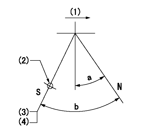
N:Pump normal
S:Stop the pump.
(1)Drive side
(2)Use the hole at R = aa
(3)Rack position bb
(4)Stopper bolt setting
----------
aa=36mm bb=4.3-0.5mm
----------
a=10.5deg+-5deg b=55deg+7deg-5deg
----------
aa=36mm bb=4.3-0.5mm
----------
a=10.5deg+-5deg b=55deg+7deg-5deg
0000001501 MICRO SWITCH
Adjustment of the micro-switch
Adjust the bolt to obtain the following lever position when the micro-switch is ON.
(1)Speed N1
(2)Rack position Ra
----------
N1=325r/min Ra=6.3+-0.1mm
----------
----------
N1=325r/min Ra=6.3+-0.1mm
----------
Timing setting

(1)Pump vertical direction
(2)Coupling's key groove position at No 1 cylinder's beginning of injection
(3)B.T.D.C.: aa
(4)-
----------
aa=14deg
----------
a=(40deg)
----------
aa=14deg
----------
a=(40deg)
Information:
Stopping the engine immediately after it has been working under load can result in overheating and accelerated wear of the engine components. Follow the stopping procedures, outlined below, to allow the engine to cool. Excessive temperatures in the turbocharger center housing will cause oil coking problems.
Prior to stopping an engine that is being operated at low loads, run the engine at LOW IDLE for 30 seconds before stopping. If the engine is being operated at high load, then it should be run at LOW IDLE for five minutes to reduce and stabilize internal engine coolant and oil temperatures before stopping.Make sure the Engine Stopping procedure is understood. The engine may be shutdown in several ways. To manually stop the engine, refer to the following information and instructions.Emergency Stop Procedure
The Emergency Stop Pushbutton (ESPB) and Emergency stop controls are for EMERGENCY use ONLY. DO NOT use for normal stopping procedure. Emergency Stop controls should only be used when an emergency exists, and not used to routinely stop the engine. Do NOT start the engine until the problem necessitating the emergency stop has been located and corrected.
* Emergency stops may be made through the Emergency Stop Pushbutton (ESPB). If the need for emergency engine shutdown occurs, push the EMERGENCY STOP Pushbutton located on the control panel or the engine junction box. This will activate the air and/or fuel shutoffs. Reset the EMERGENCY STOP Pushbutton (pull out and rotate the button in the direction indicated on the button). Some EMERGENCY STOP Pushbuttons can be pulled out to reset, not requiring any rotation.Manual Stop Procedure
1. Reduce the engine speed to LOW IDLE. Shift the marine transmission to NEUTRAL and secure the vessel.2. Increase engine speed to no more than half engine speed for five minutes to cool the engine. Reduce engine speed to LOW IDLE. 3. Check the crankcase oil level while the engine is idling. Maintain the oil level between the ADD and FULL marks on the CHECK WITH ENGINE RUNNING or ENGINE AT LOW IDLE WITH OIL WARM side of the dipstick.4. Shift the marine transmission to FORWARD or REVERSE. Check the marine transmission oil level at ENGINE AT LOW IDLE WITH OIL WARM. Maintain oil level between the ADD and FULL marks on the dipstick. Shift the marine transmission back to NEUTRAL.5. The engine may be stopped by using one of the following engine mounted controls.Toggle Switch
Move OEM or customer supplied toggle switch to the OFF position to shut off the fuel shutoff solenoid.Manual Fuel Shutoff Lever (All Engines)
Do not use the emergency shutoff control for a normal stopping procedure. A manual shutdown shaft is provided to override the governor solenoid. This shutdown will only move the fuel control linkage to the fuel OFF position to starve the engine of fuel. It does not shut off the air inlet. The engine will coast to a stop. Be sure to secure any external system components that have been operating to support the engine operation.After Stopping the Engine
1. If freezing temperatures
Have questions with 106873-2890?
Group cross 106873-2890 ZEXEL
Mitsubishi
Mitsubishi
106873-2890
9 400 618 397
ME160956
INJECTION-PUMP ASSEMBLY
8M20-2
8M20-2