Information injection-pump assembly
BOSCH
9 400 618 391
9400618391
ZEXEL
106873-2831
1068732831
MITSUBISHI
ME160842
me160842
Rating:
Service parts 106873-2831 INJECTION-PUMP ASSEMBLY:
1.
_
7.
COUPLING PLATE
8.
_
9.
_
11.
Nozzle and Holder
12.
Open Pre:MPa(Kqf/cm2)
17.7{180}/24.5{250}
15.
NOZZLE SET
Include in #1:
106873-2831
as INJECTION-PUMP ASSEMBLY
Cross reference number
BOSCH
9 400 618 391
9400618391
ZEXEL
106873-2831
1068732831
MITSUBISHI
ME160842
me160842
Zexel num
Bosch num
Firm num
Name
106873-2831
9 400 618 391
ME160842 MITSUBISHI
INJECTION-PUMP ASSEMBLY
8M20-I K
8M20-I K
Calibration Data:
Adjustment conditions
Test oil
1404 Test oil ISO4113 or {SAEJ967d}
1404 Test oil ISO4113 or {SAEJ967d}
Test oil temperature
degC
40
40
45
Nozzle and nozzle holder
105780-8140
Bosch type code
EF8511/9A
Nozzle
105780-0000
Bosch type code
DN12SD12T
Nozzle holder
105780-2080
Bosch type code
EF8511/9
Opening pressure
MPa
17.2
Opening pressure
kgf/cm2
175
Injection pipe
Outer diameter - inner diameter - length (mm) mm 8-3-600
Outer diameter - inner diameter - length (mm) mm 8-3-600
Overflow valve
131424-7920
Overflow valve opening pressure
kPa
255
221
289
Overflow valve opening pressure
kgf/cm2
2.6
2.25
2.95
Tester oil delivery pressure
kPa
157
157
157
Tester oil delivery pressure
kgf/cm2
1.6
1.6
1.6
Direction of rotation (viewed from drive side)
Right R
Right R
Injection timing adjustment
Direction of rotation (viewed from drive side)
Right R
Right R
Injection order
1-2-7-3-
4-5-6-8
Pre-stroke
mm
4.4
4.37
4.43
Beginning of injection position
Governor side NO.1
Governor side NO.1
Difference between angles 1
Cyl.1-2 deg. 45 44.75 45.25
Cyl.1-2 deg. 45 44.75 45.25
Difference between angles 2
Cal 1-7 deg. 90 89.75 90.25
Cal 1-7 deg. 90 89.75 90.25
Difference between angles 3
Cal 1-3 deg. 135 134.75 135.25
Cal 1-3 deg. 135 134.75 135.25
Difference between angles 4
Cal 1-4 deg. 180 179.75 180.25
Cal 1-4 deg. 180 179.75 180.25
Difference between angles 5
Cal 1-5 deg. 225 224.75 225.25
Cal 1-5 deg. 225 224.75 225.25
Difference between angles 6
Cal 1-6 deg. 270 269.75 270.25
Cal 1-6 deg. 270 269.75 270.25
Difference between angles 7
Cal 1-8 deg. 315 314.75 315.25
Cal 1-8 deg. 315 314.75 315.25
Injection quantity adjustment
Adjusting point
-
Rack position
10.2
Pump speed
r/min
650
650
650
Each cylinder's injection qty
mm3/st.
147.5
143.1
151.9
Basic
*
Fixing the rack
*
Standard for adjustment of the maximum variation between cylinders
*
Injection quantity adjustment_02
Adjusting point
C
Rack position
6.4+-0.5
Pump speed
r/min
225
225
225
Each cylinder's injection qty
mm3/st.
18
15.3
20.7
Fixing the rack
*
Standard for adjustment of the maximum variation between cylinders
*
Injection quantity adjustment_03
Adjusting point
A
Rack position
R1(10.2)
Pump speed
r/min
650
650
650
Average injection quantity
mm3/st.
147.5
146.5
148.5
Basic
*
Fixing the lever
*
Injection quantity adjustment_04
Adjusting point
B
Rack position
R1+0.9
Pump speed
r/min
1100
1100
1100
Average injection quantity
mm3/st.
164.5
160.5
168.5
Fixing the lever
*
Injection quantity adjustment_05
Adjusting point
E
Rack position
-
Pump speed
r/min
100
100
100
Average injection quantity
mm3/st.
180
160
200
Fixing the lever
*
Remarks
After startup boost setting
After startup boost setting
Timer adjustment
Pump speed
r/min
900--
Advance angle
deg.
0
0
0
Remarks
Start
Start
Timer adjustment_02
Pump speed
r/min
850
Advance angle
deg.
0.5
Timer adjustment_03
Pump speed
r/min
1100
Advance angle
deg.
4.5
4
5
Remarks
Finish
Finish
Test data Ex:
Governor adjustment
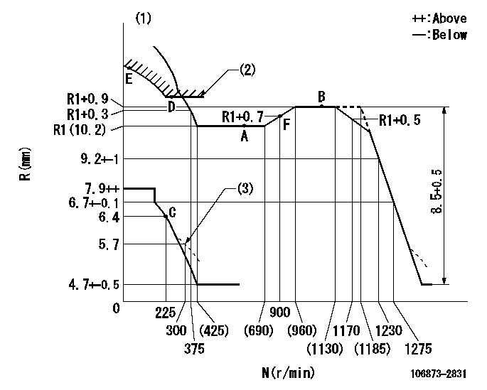
N:Pump speed
R:Rack position (mm)
(1)Tolerance for racks not indicated: +-0.05mm.
(2)Excess fuel setting for starting: SXL
(3)Damper spring setting
----------
SXL=11.3+-0.1mm
----------
----------
SXL=11.3+-0.1mm
----------
Speed control lever angle
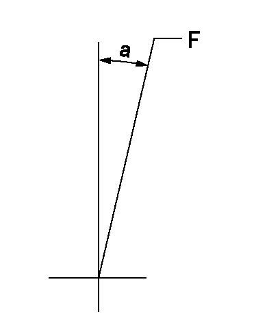
F:Full speed
----------
----------
a=(16deg)+-5deg
----------
----------
a=(16deg)+-5deg
0000000901

F:Full load
I:Idle
(1)Stopper bolt setting
----------
----------
a=10deg+-5deg b=29.5deg+-3deg
----------
----------
a=10deg+-5deg b=29.5deg+-3deg
Stop lever angle
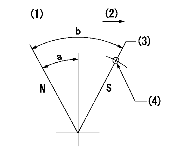
N:Pump normal
S:Stop the pump.
(1)Drive side stop lever
(2)Drive side
(3)Rack position = aa
(4)Use the hole at R = bb
----------
aa=3.7-0.5mm bb=28mm
----------
a=28.5deg+-5deg b=57deg+7deg-5deg
----------
aa=3.7-0.5mm bb=28mm
----------
a=28.5deg+-5deg b=57deg+7deg-5deg
0000001501 MICRO SWITCH
Adjustment of the micro-switch
Adjust the bolt to obtain the following lever position when the micro-switch is ON.
(1)Speed N1
(2)Rack position Ra
----------
N1=325r/min Ra=5.9+-0.1mm
----------
----------
N1=325r/min Ra=5.9+-0.1mm
----------
0000001601 GOVERNOR TORQUE CONTROL

Dr:Torque control stroke
(A): Without torque control spring capsule
1. Adjustment procedures
(1)Procedure is the same as that for the RFD (former type), except that the positive torque control stroke must be determined at the full lever setting.
2. Procedures for adjustment
(1)Remove the torque control spring capsule.
(2)Operate the pump at approximately N1. (End of idling spring operation < N1.)
(3)Tilt the lever to the full side.
(4)Set so that R = RF.
(5)Increase the speed by pushing in the screw (attached to the bracket on the rear of the tension lever) through the adjusting window.
(6)Adjust so that the torque control stroke Dr1 can be obtained.
(7)Align N2 and N3 with the torque control spring capsule.
3. Final confirmation
(1)After final confirmation, temporarily set the load lever to N = N1, R = idling position.
(2)From this condition, increase speed to N = N4.
(3)Confirm that positive torque control stroke is Dr2.
----------
N1=500r/min N2=(690)r/min N3=(960)r/min N4=1100r/min RF=R1(10.2)mm Dr1=0.9mm Dr2=0+0.3mm
----------
----------
N1=500r/min N2=(690)r/min N3=(960)r/min N4=1100r/min RF=R1(10.2)mm Dr1=0.9mm Dr2=0+0.3mm
----------
Timing setting

(1)Pump vertical direction
(2)Coupling's key groove position at No 1 cylinder's beginning of injection
(3)B.T.D.C.: aa
(4)-
----------
aa=12deg
----------
a=(40deg)
----------
aa=12deg
----------
a=(40deg)
Information:
Lubricant Viscosity Chart
Commercial Oils
Failure to follow the commercial oil recommendations can cause shortened engine life due to piston carbon deposits, liner bore polish and/or abnormally higher increasing oil consumption.API CC and CD oils are unacceptable in this Caterpillar diesel engine.
* API specifications CF-4, CF-4/SH or CF-4/SGThe oil specifications above provide guidelines for the selection of commercial products. They may require shortened oil change intervals as determined by close monitoring of oil condition with Scheduled Oil Sampling (S O S). The same viscosity grades are recommended for commercial oils as for CAT oils.Lubricant Total Base Number (TBN)
New engine oil must have a TBN of 20 times (for Precombustion Chamber engines) and 10 times (for direct injection engines) the percent fuel sulfur as measured by ASTM (American Society if Testing Materials) D2896 method. Refer to the Fuel Specifications in this manual for additional information.Caterpillar DI Engines Only
Additional Notes
The percentage of sulfur in the fuel will affect the engine oil recommendations. For fuel sulfur effects, the ASTM D2896 procedure can be used to evaluate the residual neutralization properties of an engine oil. The sulfur products formation depends on the fuel sulfur content, oil formulation, crankcase blowby, engine operating conditions and ambient temperature.The fuel sulfur neutralization of today's new oil formulations along with direct injection (DI) system engines are more effective. Field results indicate that direct injection combustion (DI) systems and the oils now recommended for these engines will operate at an oil TBN equal to 10 times the fuel sulfur above 0.5% and using API CF-4 oils. Caterpillar requirements reflect this value of 10 times for DI engines.Caterpillar still maintains 20 times TBN value for precombustion chamber (PC) engines when using API CD, CE or CF-4 oil when related to fuel sulfur above 0.5%. Used oil analysis should be a part of the overall program to provide the assurance that a particular engine installation with all its parameters (engine, oil, operation, maintenance and fuel) are under control. Engines built prior to 1990 can continue to use DEO-CD single grade viscosity oil or commercial oils provided the engine operates to user satisfaction. Consult with your Caterpillar dealer for the latest lubrication recommendations.Synthetic Base Stock Oils (SPC)
The performance characteristics of the oil depends on the base oil and the additives. The additives in the oil will vary according to the properties of the base oil and the environment in which the oil will perform its function.Synthetic base stock oils are acceptable for use in Caterpillar engines if these oils meet the performance requirements specified for a particular compartment. The performance requirements for engines using synthetic oils is API CF-4 with API CE as an alternative.The use of a synthetic base stock oil does NOT allow extension of the oil drain period simply because of the use of synthetic oil. Any drain period extension must be validated by S O S (oil analysis and test evaluation) to ensure no excessive component wear occurs in a particular application.The synthetic oils have naturally low pour points
Have questions with 106873-2831?
Group cross 106873-2831 ZEXEL
Mitsubishi
Mitsubishi
106873-2831
9 400 618 391
ME160842
INJECTION-PUMP ASSEMBLY
8M20-I
8M20-I
