Information injection-pump assembly
ZEXEL
106873-2800
1068732800

Rating:
Cross reference number
ZEXEL
106873-2800
1068732800
Zexel num
Bosch num
Firm num
Name
106873-2800
INJECTION-PUMP ASSEMBLY
Calibration Data:
Adjustment conditions
Test oil
1404 Test oil ISO4113 or {SAEJ967d}
1404 Test oil ISO4113 or {SAEJ967d}
Test oil temperature
degC
40
40
45
Nozzle and nozzle holder
105780-8140
Bosch type code
EF8511/9A
Nozzle
105780-0000
Bosch type code
DN12SD12T
Nozzle holder
105780-2080
Bosch type code
EF8511/9
Opening pressure
MPa
17.2
Opening pressure
kgf/cm2
175
Injection pipe
Outer diameter - inner diameter - length (mm) mm 8-3-600
Outer diameter - inner diameter - length (mm) mm 8-3-600
Overflow valve
131424-4620
Overflow valve opening pressure
kPa
255
221
289
Overflow valve opening pressure
kgf/cm2
2.6
2.25
2.95
Tester oil delivery pressure
kPa
157
157
157
Tester oil delivery pressure
kgf/cm2
1.6
1.6
1.6
Direction of rotation (viewed from drive side)
Right R
Right R
Injection timing adjustment
Direction of rotation (viewed from drive side)
Right R
Right R
Injection order
1-2-7-3-
4-5-6-8
Pre-stroke
mm
4.8
4.75
4.85
Beginning of injection position
Governor side NO.1
Governor side NO.1
Difference between angles 1
Cyl.1-2 deg. 45 44.5 45.5
Cyl.1-2 deg. 45 44.5 45.5
Difference between angles 2
Cal 1-7 deg. 90 89.5 90.5
Cal 1-7 deg. 90 89.5 90.5
Difference between angles 3
Cal 1-3 deg. 135 134.5 135.5
Cal 1-3 deg. 135 134.5 135.5
Difference between angles 4
Cal 1-4 deg. 180 179.5 180.5
Cal 1-4 deg. 180 179.5 180.5
Difference between angles 5
Cal 1-5 deg. 225 224.5 225.5
Cal 1-5 deg. 225 224.5 225.5
Difference between angles 6
Cal 1-6 deg. 270 269.5 270.5
Cal 1-6 deg. 270 269.5 270.5
Difference between angles 7
Cal 1-8 deg. 315 314.5 315.5
Cal 1-8 deg. 315 314.5 315.5
Injection quantity adjustment
Adjusting point
-
Rack position
10.4
Pump speed
r/min
650
650
650
Each cylinder's injection qty
mm3/st.
140.4
136.2
144.6
Basic
*
Fixing the rack
*
Standard for adjustment of the maximum variation between cylinders
*
Injection quantity adjustment_02
Adjusting point
C
Rack position
6.8+-0.5
Pump speed
r/min
225
225
225
Each cylinder's injection qty
mm3/st.
19
16.1
21.9
Fixing the rack
*
Standard for adjustment of the maximum variation between cylinders
*
Injection quantity adjustment_03
Adjusting point
A
Rack position
R1(10.4)
Pump speed
r/min
650
650
650
Average injection quantity
mm3/st.
140.4
139.4
141.4
Basic
*
Fixing the lever
*
Injection quantity adjustment_04
Adjusting point
B
Rack position
R1-0.25
Pump speed
r/min
1100
1100
1100
Average injection quantity
mm3/st.
128
126
130
Fixing the lever
*
Injection quantity adjustment_05
Adjusting point
E
Rack position
-
Pump speed
r/min
100
100
100
Average injection quantity
mm3/st.
145
105
185
Fixing the lever
*
Remarks
After startup boost setting
After startup boost setting
Test data Ex:
Governor adjustment
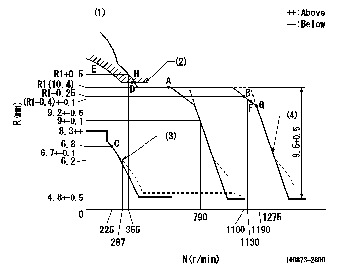
N:Pump speed
R:Rack position (mm)
(1)Tolerance for racks not indicated: +-0.05mm.
(2)Excess fuel setting for starting: SXL
(3)Damper spring setting
(4)When air cylinder is operating.
----------
SXL=10.6+-0.1mm
----------
----------
SXL=10.6+-0.1mm
----------
Timer adjustment

(1)Adjusting range
(2)Step response time
(N): Speed of the pump
(L): Load
(theta) Advance angle
(Srd1) Step response time 1
(Srd2) Step response time 2
1. Adjusting conditions for the variable timer
(1)Adjust the clearance between the pickup and the protrusion to L.
----------
L=1-0.2mm N2=800r/min C2=(8.8)deg t1=2.5--sec. t2=2.5--sec.
----------
N1=750++r/min P1=0kPa(0kgf/cm2) P2=392kPa(4kgf/cm2) C1=8.8+-0.3deg R01=0/4load R02=4/4load
----------
L=1-0.2mm N2=800r/min C2=(8.8)deg t1=2.5--sec. t2=2.5--sec.
----------
N1=750++r/min P1=0kPa(0kgf/cm2) P2=392kPa(4kgf/cm2) C1=8.8+-0.3deg R01=0/4load R02=4/4load
Speed control lever angle
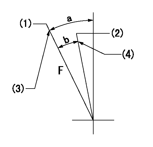
F:Full speed
(1)Set the pump speed at aa
(2)Set the pump speed at bb.
(3)Stopper bolt setting
(4)Stopper bolt setting
----------
aa=1275r/min bb=790r/min
----------
a=(22deg)+-5deg b=(5.5deg)+-5deg
----------
aa=1275r/min bb=790r/min
----------
a=(22deg)+-5deg b=(5.5deg)+-5deg
0000000901

F:Full load
I:Idle
(1)Stopper bolt setting
----------
----------
a=10deg+-5deg b=21deg+-3deg
----------
----------
a=10deg+-5deg b=21deg+-3deg
Stop lever angle
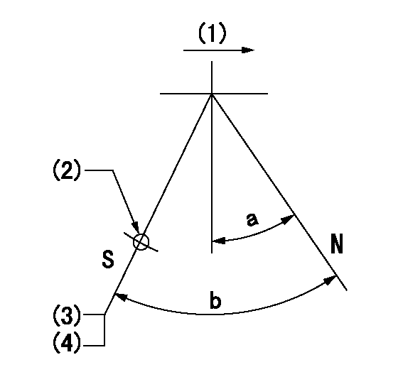
N:Pump normal
S:Stop the pump.
(1)Drive side
(2)Use the hole at R = aa
(3)Rack position bb
(4)Stopper bolt setting
----------
aa=36mm bb=4.3-0.5mm
----------
a=10.5deg+-5deg b=55deg+7deg-5deg
----------
aa=36mm bb=4.3-0.5mm
----------
a=10.5deg+-5deg b=55deg+7deg-5deg
0000001501 MICRO SWITCH
Adjustment of the micro-switch
Adjust the bolt to obtain the following lever position when the micro-switch is ON.
(1)Speed N1
(2)Rack position Ra
----------
N1=325r/min Ra=6.3+-0.1mm
----------
----------
N1=325r/min Ra=6.3+-0.1mm
----------
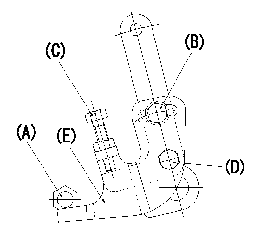
0000001601 RACK SENSOR

V1:Supply voltage
V2f:Full side output voltage
V2i:Idle side output voltage
(A) Black
(B) Yellow
(C) Red
(D) Trimmer
(E): Shaft
(F) Nut
(G) Load lever
1. Load sensor adjustment
(1)Connect as shown in the above diagram and apply supply voltage V1.
(2)Hold the load lever (G) against the full side.
(3)Turn the shaft so that the voltage between (A) and (B) is V2.
(4)Hold the load lever (G) against the idle side.
(5)Adjust (D) so that the voltage between (A) and (B) is V2i.
(6)Repeat the above adjustments.
(7)Tighten the nut (F) at the point satisfying the standards.
(8)Hold the load lever against the full side stopper and the idle side stopper.
(9)At this time, confirm that the full side output voltage is V2f and the idle side output voltage is V2i.
----------
V1=5+-0.02V V2f=0.15+0.03V V2i=2.35-0.03V
----------
----------
V1=5+-0.02V V2f=0.15+0.03V V2i=2.35-0.03V
----------
0000001701 LEVER
(A) Stopper
(B) bolt
Bolt c
(D) Bolt
(E) Lever
Speed lever angle and speed lever setting procedure
(1)Set the speed lever so that speed N = N1.
(2)With the lever (E) contacting the stopper (A), fully tighten bolts (B) and (D).
(3)Screw in bolt (C) and lock.
(4)Set the speed lever at the full position so that N = N2.
----------
N1=790r/min N2=1275r/min
----------
----------
N1=790r/min N2=1275r/min
----------
Timing setting

(1)Pump vertical direction
(2)Coupling's key groove position at No 1 cylinder's beginning of injection
(3)B.T.D.C.: aa
(4)-
----------
aa=12deg
----------
a=(40deg)
----------
aa=12deg
----------
a=(40deg)
Information:
4. Start the engine. After starting, travel with caution, at minimum speed.5. To stop the vessel, stop the engine. Remove the bolts engaging the clutch when the engine is stopped. Disassemble and inspect the clutch plates for warping and cracking. Damage can occur by having the clutch plates mechanically engaged. Under severe operating conditions, the marine gear should be disassembled and all bearings inspected closely.Engine Jacket Water Pump Failure
If the engine jacket water pump should fail, fresh water can be supplied to the engine jacket using the emergency water system.
Tee Connector (1), Shut Off Valve (2), Emergency Jacket Water Pump (3), Tee Connector (4) & Shut Off Valve (5).1. Stop the engine. If the water pump bearing has failed, the water pump does NOT need to be removed.2. Open valve (2) between the emergency pump and oil cooler connection. 3. Place the diverter valve handle in the EMERGENCY position.4. Start and prime the emergency jacket water pump (3). Allow air to escape from the emergency cooling system lines.5. Check coolant level in the expansion tank. Add coolant if required.6. Start the engine. Always start the engine according to the required Engine Starting procedure described in this manual. Engage marine gear and operate vessel at normal speed. If the engine jacket water coolant is lost (i.e. water line rupture or leak) and an insufficient supply of fresh water is available to replenish the system, raw water may be pumped through the engine.a. Stop the engine and make the necessary water pump and lines connections to pump raw water into the jacket water system and back to the source.b. Remove the temperature regulating thermostats from the regulator housing and install housing cover.c. Start and prime the emergency pump.d. Start the engine and allow to idle at low idle. Always start the engine according to the required Engine Starting procedure described in this manual. Engage the marine gear forward clutch. Operate the engine at the lowest speed for the existing weather conditions.e. Maintain engine temperatures as low as possible to minimize deposits in the engine and corrosion of components. Have the engine jacket water system completely disassembled, cleaned and inspected after reaching port. Replace all parts which are corroded or damaged.Engine Raw Water Pump Failure
The
Have questions with 106873-2800?
Group cross 106873-2800 ZEXEL
106873-2800
INJECTION-PUMP ASSEMBLY