Information injection-pump assembly
BOSCH
9 400 618 375
9400618375
ZEXEL
106873-2673
1068732673
MITSUBISHI
ME160577
me160577
Rating:
Service parts 106873-2673 INJECTION-PUMP ASSEMBLY:
1.
_
7.
COUPLING PLATE
8.
_
9.
_
11.
Nozzle and Holder
ME160666
12.
Open Pre:MPa(Kqf/cm2)
17.7{180}/24.5{250}
15.
NOZZLE SET
Include in #1:
106873-2673
as INJECTION-PUMP ASSEMBLY
Cross reference number
BOSCH
9 400 618 375
9400618375
ZEXEL
106873-2673
1068732673
MITSUBISHI
ME160577
me160577
Zexel num
Bosch num
Firm num
Name
106873-2673
9 400 618 375
ME160577 MITSUBISHI
INJECTION-PUMP ASSEMBLY
8M20-I * K 14CD INJECTION PUMP ASSY PE8P PE
8M20-I * K 14CD INJECTION PUMP ASSY PE8P PE
Calibration Data:
Adjustment conditions
Test oil
1404 Test oil ISO4113 or {SAEJ967d}
1404 Test oil ISO4113 or {SAEJ967d}
Test oil temperature
degC
40
40
45
Nozzle and nozzle holder
105780-8140
Bosch type code
EF8511/9A
Nozzle
105780-0000
Bosch type code
DN12SD12T
Nozzle holder
105780-2080
Bosch type code
EF8511/9
Opening pressure
MPa
17.2
Opening pressure
kgf/cm2
175
Injection pipe
Outer diameter - inner diameter - length (mm) mm 8-3-600
Outer diameter - inner diameter - length (mm) mm 8-3-600
Overflow valve
131424-7920
Overflow valve opening pressure
kPa
255
221
289
Overflow valve opening pressure
kgf/cm2
2.6
2.25
2.95
Tester oil delivery pressure
kPa
157
157
157
Tester oil delivery pressure
kgf/cm2
1.6
1.6
1.6
Direction of rotation (viewed from drive side)
Right R
Right R
Injection timing adjustment
Direction of rotation (viewed from drive side)
Right R
Right R
Injection order
1-2-7-3-
4-5-6-8
Pre-stroke
mm
4.4
4.37
4.43
Beginning of injection position
Governor side NO.1
Governor side NO.1
Difference between angles 1
Cyl.1-2 deg. 45 44.75 45.25
Cyl.1-2 deg. 45 44.75 45.25
Difference between angles 2
Cal 1-7 deg. 90 89.75 90.25
Cal 1-7 deg. 90 89.75 90.25
Difference between angles 3
Cal 1-3 deg. 135 134.75 135.25
Cal 1-3 deg. 135 134.75 135.25
Difference between angles 4
Cal 1-4 deg. 180 179.75 180.25
Cal 1-4 deg. 180 179.75 180.25
Difference between angles 5
Cal 1-5 deg. 225 224.75 225.25
Cal 1-5 deg. 225 224.75 225.25
Difference between angles 6
Cal 1-6 deg. 270 269.75 270.25
Cal 1-6 deg. 270 269.75 270.25
Difference between angles 7
Cal 1-8 deg. 315 314.75 315.25
Cal 1-8 deg. 315 314.75 315.25
Injection quantity adjustment
Adjusting point
-
Rack position
10.2
Pump speed
r/min
650
650
650
Each cylinder's injection qty
mm3/st.
147.5
143.1
151.9
Basic
*
Fixing the rack
*
Standard for adjustment of the maximum variation between cylinders
*
Injection quantity adjustment_02
Adjusting point
C
Rack position
6.4+-0.5
Pump speed
r/min
225
225
225
Each cylinder's injection qty
mm3/st.
18
15.3
20.7
Fixing the rack
*
Standard for adjustment of the maximum variation between cylinders
*
Injection quantity adjustment_03
Adjusting point
A
Rack position
R1(10.2)
Pump speed
r/min
650
650
650
Average injection quantity
mm3/st.
147.5
146.5
148.5
Basic
*
Fixing the lever
*
Injection quantity adjustment_04
Adjusting point
B
Rack position
R1+0.9
Pump speed
r/min
1100
1100
1100
Average injection quantity
mm3/st.
164.5
160.5
168.5
Fixing the lever
*
Injection quantity adjustment_05
Adjusting point
E
Rack position
-
Pump speed
r/min
100
100
100
Average injection quantity
mm3/st.
180
160
200
Fixing the lever
*
Remarks
After startup boost setting
After startup boost setting
Timer adjustment
Pump speed
r/min
900--
Advance angle
deg.
0
0
0
Remarks
Start
Start
Timer adjustment_02
Pump speed
r/min
850
Advance angle
deg.
0.5
Timer adjustment_03
Pump speed
r/min
1100
Advance angle
deg.
4.5
4
5
Remarks
Finish
Finish
Test data Ex:
Governor adjustment
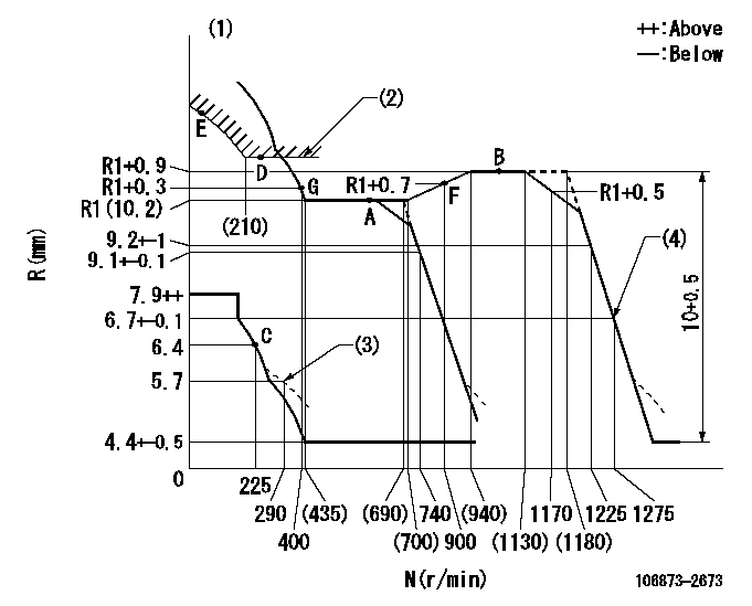
N:Pump speed
R:Rack position (mm)
(1)Tolerance for racks not indicated: +-0.05mm.
(2)Excess fuel setting for starting: SXL
(3)Damper spring setting
(4)When air cylinder is operating.
----------
SXL=11.3+-0.1mm
----------
----------
SXL=11.3+-0.1mm
----------
Speed control lever angle
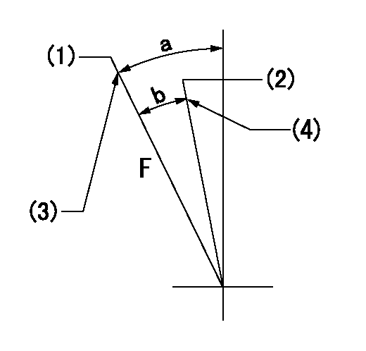
F:Full speed
(1)Set the pump speed at aa
(2)Set the pump speed at bb.
(3)Stopper bolt setting
(4)Stopper bolt setting
----------
aa=1275r/min bb=740r/min
----------
a=19.5deg+-5deg b=(8deg)+-5deg
----------
aa=1275r/min bb=740r/min
----------
a=19.5deg+-5deg b=(8deg)+-5deg
0000000901

F:Full load
I:Idle
(1)Stopper bolt setting
----------
----------
a=10deg+-5deg b=21.5deg+-3deg
----------
----------
a=10deg+-5deg b=21.5deg+-3deg
Stop lever angle
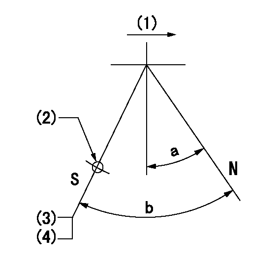
N:Pump normal
S:Stop the pump.
(1)Drive side
(2)Use the hole at R = aa
(3)Rack position bb
(4)Stopper bolt setting
----------
aa=36mm bb=3.7-0.5mm
----------
a=10.5deg+-5deg b=57deg+7deg-5deg
----------
aa=36mm bb=3.7-0.5mm
----------
a=10.5deg+-5deg b=57deg+7deg-5deg
0000001501 MICRO SWITCH
Adjustment of the micro-switch
Adjust the bolt to obtain the following lever position when the micro-switch is ON.
(1)Speed N1
(2)Rack position Ra
----------
N1=325r/min Ra=5.9+-0.1mm
----------
----------
N1=325r/min Ra=5.9+-0.1mm
----------
0000001601 GOVERNOR TORQUE CONTROL

Dr:Torque control stroke
(A): Without torque control spring capsule
1. Adjustment procedures
(1)Procedure is the same as that for the RFD (former type), except that the positive torque control stroke must be determined at the full lever setting.
2. Procedures for adjustment
(1)Remove the torque control spring capsule.
(2)Operate the pump at approximately N1. (End of idling spring operation < N1.)
(3)Tilt the lever to the full side.
(4)Set so that R = RF.
(5)Increase the speed by pushing in the screw (attached to the bracket on the rear of the tension lever) through the adjusting window.
(6)Adjust so that the torque control stroke Dr1 can be obtained.
(7)Align N2 and N3 with the torque control spring capsule.
3. Final confirmation
(1)After final confirmation, temporarily set the load lever to N = N1, R = idling position.
(2)From this condition, increase speed to N = N4.
(3)Confirm that positive torque control stroke is Dr2.
----------
N1=500r/min N2=(700)r/min N3=(940)r/min N4=1100r/min RF=10.2mm Dr1=0.9mm Dr2=0+0.3mm
----------
----------
N1=500r/min N2=(700)r/min N3=(940)r/min N4=1100r/min RF=10.2mm Dr1=0.9mm Dr2=0+0.3mm
----------
Timing setting

(1)Pump vertical direction
(2)Coupling's key groove position at No 1 cylinder's beginning of injection
(3)B.T.D.C.: aa
(4)-
----------
aa=12deg
----------
a=(40deg)
----------
aa=12deg
----------
a=(40deg)
Information:
Lubrication Specifications
Crankcase Lubricating Oils
Use oils which meet Engine Service Classification CD (MIL-L-2104D) or CD/TO-2. These are additive-type oils that have been approved for use in Caterpillar Diesel Engines.Consult the "EMA Lubricating Oils Data Book," Form SEBU5939, for a listing of CD oil brands.The proper SAE grade of oil to select is determined by the ambient temperature at which the engine is started and the maximum ambient temperature in which the engine will be operating. See chart for recommended viscosity and temperature range.To determine if the oil in the crankcase will flow in cold weather, remove the oil dipstick before starting. If the oil will flow off, the oil is fluid enough to circulate properly.Lubricating Grease
Use Multipurpose-type Grease (MPGM) which contains 3-5% molybdenum disulfide conforming to MIL-M-7866, and a suitable corrosion inhibitor. NLGI No. 2 Grade is suitable for most temperatures. Use NLGI No. 0 or No. 1 Grade for extremely low temperatures.Recommended Lubricant Viscosities
Air Starting Motor Oiler: Use SAE 10W in all temperatures.Flywheel Clutch Bearing Reservoir: Use SAE 30 in all temperatures. Fuel Specifications
No. 2 fuel oil and No. 2D diesel fuel are recommended for use in Caterpillar Diesel Engines. In extreme cold temperatures use No. 1 fuel oil or No. 1D diesel fuel.In selecting a fuel, note that distillate fuels are especially desirable because the fuel is heated to a vaporous state and condensed, thus eliminating all sediment and residue.There is considerable variation in the composition of fuels distributed under the No. 2 grade classifications. For desirable engine service it is most important to give special attention to cetane no., water and sediment, pour point, cloud point and sulphur content. USE THE LOWEST PRICE DISTILLATE FUEL WHICH MEETS THE FOLLOWING REQUIREMENTS.Water and Sediment 0.1% sedimentCetane No. (PC Engine) 35 minimum(DI Engine) 40 minimumPour Point 10°F (6°C) below ambient temperatureCloud Point No higher than ambient temperatureSulphur Content* Adjust oil change periodGravity 32-40 A.P.I. at 60°F (15.6°C)*See the topic SULPHUR CONTENT. Cetane No: This is an indication of a fuel's ignition quality and should not be less than 35 for the PC engine and 40 for the DI engine. For high altitude operation or cold weather starting, a higher cetane number is required. Water and Sediment: A good clean fuel will contain no more than 0.1% sediment and water. Dirty fuels lead to early filter plugging and in addition can result in the formation of gums and resins reducing filter and engine life. Pour Point: The pour point of the fuel has no effect on engine performance, as long as the fuel is fluid enough to flow from the fuel tank to the engine. The pour point of the fuel should be at least 10°F (6°C) below the lowest atmospheric temperature at which the engine must start and operate. In extremely cold temperatures it may be necessary to use No. 1 fuel oil or No. 1D diesel fuel. Cloud Point: Cloud point is the temperature at which wax crystals become visible and is generally above the pour point of
Have questions with 106873-2673?
Group cross 106873-2673 ZEXEL
Mitsubishi
Mitsubishi
Mitsubishi
Mitsubishi
Mitsubishi
106873-2673
9 400 618 375
ME160577
INJECTION-PUMP ASSEMBLY
8M20-I
8M20-I
