Information injection-pump assembly
BOSCH
9 400 619 461
9400619461
ZEXEL
106873-2670
1068732670
Rating:
Service parts 106873-2670 INJECTION-PUMP ASSEMBLY:
1.
_
7.
COUPLING PLATE
8.
_
9.
_
11.
Nozzle and Holder
12.
Open Pre:MPa(Kqf/cm2)
15.
NOZZLE SET
Include in #1:
106873-2670
as INJECTION-PUMP ASSEMBLY
Cross reference number
BOSCH
9 400 619 461
9400619461
ZEXEL
106873-2670
1068732670
Zexel num
Bosch num
Firm num
Name
Calibration Data:
Adjustment conditions
Test oil
1404 Test oil ISO4113 or {SAEJ967d}
1404 Test oil ISO4113 or {SAEJ967d}
Test oil temperature
degC
40
40
45
Nozzle and nozzle holder
105780-8140
Bosch type code
EF8511/9A
Nozzle
105780-0000
Bosch type code
DN12SD12T
Nozzle holder
105780-2080
Bosch type code
EF8511/9
Opening pressure
MPa
17.2
Opening pressure
kgf/cm2
175
Injection pipe
Outer diameter - inner diameter - length (mm) mm 8-3-600
Outer diameter - inner diameter - length (mm) mm 8-3-600
Overflow valve
131424-4620
Overflow valve opening pressure
kPa
255
221
289
Overflow valve opening pressure
kgf/cm2
2.6
2.25
2.95
Tester oil delivery pressure
kPa
157
157
157
Tester oil delivery pressure
kgf/cm2
1.6
1.6
1.6
Direction of rotation (viewed from drive side)
Right R
Right R
Injection timing adjustment
Direction of rotation (viewed from drive side)
Right R
Right R
Injection order
1-2-7-3-
4-5-6-8
Pre-stroke
mm
4.4
4.35
4.45
Beginning of injection position
Governor side NO.1
Governor side NO.1
Difference between angles 1
Cyl.1-2 deg. 45 44.5 45.5
Cyl.1-2 deg. 45 44.5 45.5
Difference between angles 2
Cal 1-7 deg. 90 89.5 90.5
Cal 1-7 deg. 90 89.5 90.5
Difference between angles 3
Cal 1-3 deg. 135 134.5 135.5
Cal 1-3 deg. 135 134.5 135.5
Difference between angles 4
Cal 1-4 deg. 180 179.5 180.5
Cal 1-4 deg. 180 179.5 180.5
Difference between angles 5
Cal 1-5 deg. 225 224.5 225.5
Cal 1-5 deg. 225 224.5 225.5
Difference between angles 6
Cal 1-6 deg. 270 269.5 270.5
Cal 1-6 deg. 270 269.5 270.5
Difference between angles 7
Cal 1-8 deg. 315 314.5 315.5
Cal 1-8 deg. 315 314.5 315.5
Injection quantity adjustment
Adjusting point
-
Rack position
10.4
Pump speed
r/min
650
650
650
Each cylinder's injection qty
mm3/st.
151.5
147
156
Basic
*
Fixing the rack
*
Standard for adjustment of the maximum variation between cylinders
*
Injection quantity adjustment_02
Adjusting point
C
Rack position
5.9+-0.5
Pump speed
r/min
225
225
225
Each cylinder's injection qty
mm3/st.
18
15.3
20.7
Fixing the rack
*
Standard for adjustment of the maximum variation between cylinders
*
Injection quantity adjustment_03
Adjusting point
A
Rack position
R1(10.4)
Pump speed
r/min
650
650
650
Average injection quantity
mm3/st.
151.5
150.5
152.5
Basic
*
Fixing the lever
*
Injection quantity adjustment_04
Adjusting point
B
Rack position
R1+0.75
Pump speed
r/min
1100
1100
1100
Average injection quantity
mm3/st.
161.5
157.5
165.5
Fixing the lever
*
Injection quantity adjustment_05
Adjusting point
E
Rack position
-
Pump speed
r/min
100
100
100
Average injection quantity
mm3/st.
200
160
240
Fixing the lever
*
Remarks
After startup boost setting
After startup boost setting
Timer adjustment
Pump speed
r/min
900--
Advance angle
deg.
0
0
0
Remarks
Start
Start
Timer adjustment_02
Pump speed
r/min
850
Advance angle
deg.
0.5
Timer adjustment_03
Pump speed
r/min
1100
Advance angle
deg.
4.5
4
5
Remarks
Finish
Finish
Test data Ex:
Governor adjustment
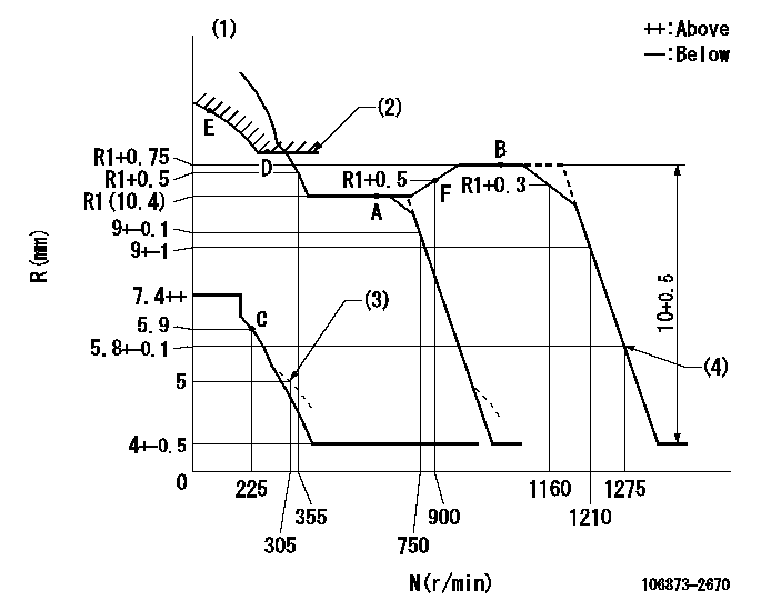
N:Pump speed
R:Rack position (mm)
(1)Tolerance for racks not indicated: +-0.05mm.
(2)Excess fuel setting for starting: SXL
(3)Damper spring setting
(4)When air cylinder is operating.
----------
SXL=11.3+-0.1mm
----------
----------
SXL=11.3+-0.1mm
----------
Speed control lever angle
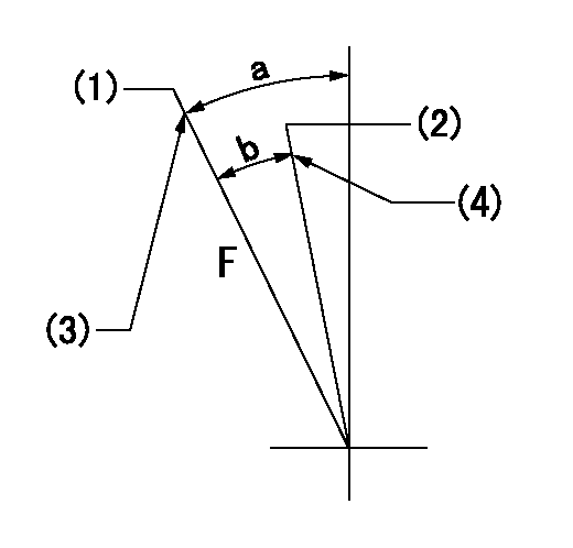
F:Full speed
(1)Set the pump speed at aa
(2)Set the pump speed at bb.
(3)Stopper bolt setting
(4)Stopper bolt setting
----------
aa=1275r/min bb=750r/min
----------
a=19.5deg+-5deg b=(8deg)+-5deg
----------
aa=1275r/min bb=750r/min
----------
a=19.5deg+-5deg b=(8deg)+-5deg
0000000901

F:Full load
I:Idle
(1)Stopper bolt setting
----------
----------
a=10deg+-5deg b=23.5deg+-3deg
----------
----------
a=10deg+-5deg b=23.5deg+-3deg
Stop lever angle
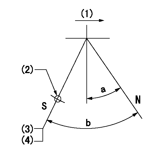
N:Pump normal
S:Stop the pump.
(1)Drive side
(2)Use the hole at R = aa
(3)Rack position bb
(4)Stopper bolt setting
----------
aa=36mm bb=3.7-0.5mm
----------
a=10.5deg+-5deg b=57deg+7deg-5deg
----------
aa=36mm bb=3.7-0.5mm
----------
a=10.5deg+-5deg b=57deg+7deg-5deg
0000001501 MICRO SWITCH
Adjustment of the micro-switch
Adjust the bolt to obtain the following lever position when the micro-switch is ON.
(1)Speed N1
(2)Rack position Ra
----------
N1=325r/min Ra=5.4+-0.1mm
----------
----------
N1=325r/min Ra=5.4+-0.1mm
----------
0000001601 GOVERNOR TORQUE CONTROL

Dr:Torque control stroke
(A): Without torque control spring capsule
1. Adjustment procedures
(1)Procedure is the same as that for the RFD (former type), except that the positive torque control stroke must be determined at the full lever setting.
2. Procedures for adjustment
(1)Remove the torque control spring capsule.
(2)Operate the pump at approximately N1. (End of idling spring operation < N1.)
(3)Tilt the lever to the full side.
(4)Set so that R = RF.
(5)Increase the speed by pushing in the screw (attached to the bracket on the rear of the tension lever) through the adjusting window.
(6)Adjust so that the torque control stroke Dr1 can be obtained.
(7)Align N2 and N3 with the torque control spring capsule.
3. Final confirmation
(1)After final confirmation, temporarily set the load lever to N = N1, R = idling position.
(2)From this condition, increase speed to N = N4.
(3)Confirm that positive torque control stroke is Dr2.
----------
N1=500r/min N2=- N3=- N4=1100r/min RF=R1(10.4)mm Dr1=0.75mm Dr2=0+0.3mm
----------
----------
N1=500r/min N2=- N3=- N4=1100r/min RF=R1(10.4)mm Dr1=0.75mm Dr2=0+0.3mm
----------
Timing setting

(1)Pump vertical direction
(2)Coupling's key groove position at No 1 cylinder's beginning of injection
(3)B.T.D.C.: aa
(4)-
----------
aa=12deg
----------
a=(40deg)
----------
aa=12deg
----------
a=(40deg)
Information:
Altitude Operation
The fuel system settings and altitude limits are stamped on the engine information plate. When an engine is moved to a higher altitude, these settings must be changed by your Caterpillar dealer in order to prevent damaging the turbocharger, and to provide maximum engine efficiency. If the engine is moved to a lower altitude than that which is stamped on the engine information plate, the engine can be operated safely; however, it will deliver less than rated horsepower, and the fuel settings should be changed by your Caterpillar dealer to obtain rated horsepower.Stopping
1. Flywheel clutch operation: Quickly pull the clutch lever to the released position. For electric set operation, see the GENERATOR SET OPERATION instructions. For Woodward Governor operation, see the topic, WOODWARD GOVERNORS, Stopping the Engine. 2. Reduce engine speed to half speed. Run for 5 minutes to cool engine.3. Reduce engine speed to low idle.4. Observe the crankcase oil level while the engine is idling. Maintain the oil level between the ADD and FULL marks on the side of the dipstick stamped, CHECK WITH ENGINE RUNNING. See the LUBRICATION AND MAINTENANCE SECTION.5. Stop the engine. After Stopping Checks And Procedures
1. Fill the fuel tank. See the LUBRICATION AND MAINTENANCE SECTION: Fuel Tank Maintenance.2. Drain the raw water system if below freezing temperatures are expected; see: Draining Raw Water System.3. If below freezing temperatures are expected, allow the engine jacket water expansion tank to cool; then check the coolant for proper antifreeze protection. Add permanent-type antifreeze, if required.4. Repair any leaks, make major adjustments, tighten loose bolts, etc.5. Observe the Service Meter reading. Perform the periodic maintenance as instructed in the LUBRICATION AND MAINTENANCE CHART.
SERVICE METER