Information injection-pump assembly
ZEXEL
106873-2662
1068732662

Rating:
Cross reference number
ZEXEL
106873-2662
1068732662
Zexel num
Bosch num
Firm num
Name
106873-2662
INJECTION-PUMP ASSEMBLY
Calibration Data:
Adjustment conditions
Test oil
1404 Test oil ISO4113 or {SAEJ967d}
1404 Test oil ISO4113 or {SAEJ967d}
Test oil temperature
degC
40
40
45
Nozzle and nozzle holder
105780-8140
Bosch type code
EF8511/9A
Nozzle
105780-0000
Bosch type code
DN12SD12T
Nozzle holder
105780-2080
Bosch type code
EF8511/9
Opening pressure
MPa
17.2
Opening pressure
kgf/cm2
175
Injection pipe
Outer diameter - inner diameter - length (mm) mm 8-3-600
Outer diameter - inner diameter - length (mm) mm 8-3-600
Overflow valve
131424-7920
Overflow valve opening pressure
kPa
255
221
289
Overflow valve opening pressure
kgf/cm2
2.6
2.25
2.95
Tester oil delivery pressure
kPa
157
157
157
Tester oil delivery pressure
kgf/cm2
1.6
1.6
1.6
Direction of rotation (viewed from drive side)
Right R
Right R
Injection timing adjustment
Direction of rotation (viewed from drive side)
Right R
Right R
Injection order
1-2-7-3-
4-5-6-8
Pre-stroke
mm
4.4
4.37
4.43
Beginning of injection position
Governor side NO.1
Governor side NO.1
Difference between angles 1
Cyl.1-2 deg. 45 44.75 45.25
Cyl.1-2 deg. 45 44.75 45.25
Difference between angles 2
Cal 1-7 deg. 90 89.75 90.25
Cal 1-7 deg. 90 89.75 90.25
Difference between angles 3
Cal 1-3 deg. 135 134.75 135.25
Cal 1-3 deg. 135 134.75 135.25
Difference between angles 4
Cal 1-4 deg. 180 179.75 180.25
Cal 1-4 deg. 180 179.75 180.25
Difference between angles 5
Cal 1-5 deg. 225 224.75 225.25
Cal 1-5 deg. 225 224.75 225.25
Difference between angles 6
Cal 1-6 deg. 270 269.75 270.25
Cal 1-6 deg. 270 269.75 270.25
Difference between angles 7
Cal 1-8 deg. 315 314.75 315.25
Cal 1-8 deg. 315 314.75 315.25
Injection quantity adjustment
Adjusting point
-
Rack position
10.2
Pump speed
r/min
650
650
650
Each cylinder's injection qty
mm3/st.
147.5
143.1
151.9
Basic
*
Fixing the rack
*
Standard for adjustment of the maximum variation between cylinders
*
Injection quantity adjustment_02
Adjusting point
C
Rack position
6.4+-0.5
Pump speed
r/min
225
225
225
Each cylinder's injection qty
mm3/st.
18
15.3
20.7
Fixing the rack
*
Standard for adjustment of the maximum variation between cylinders
*
Injection quantity adjustment_03
Adjusting point
A
Rack position
R1(10.2)
Pump speed
r/min
650
650
650
Average injection quantity
mm3/st.
147.5
146.5
148.5
Basic
*
Fixing the lever
*
Injection quantity adjustment_04
Adjusting point
B
Rack position
R1+0.9
Pump speed
r/min
1100
1100
1100
Average injection quantity
mm3/st.
164.5
160.5
168.5
Fixing the lever
*
Injection quantity adjustment_05
Adjusting point
E
Rack position
-
Pump speed
r/min
100
100
100
Average injection quantity
mm3/st.
180
160
200
Fixing the lever
*
Remarks
After startup boost setting
After startup boost setting
Timer adjustment
Pump speed
r/min
900--
Advance angle
deg.
0
0
0
Remarks
Start
Start
Timer adjustment_02
Pump speed
r/min
850
Advance angle
deg.
0.5
Timer adjustment_03
Pump speed
r/min
1100
Advance angle
deg.
4.5
4
5
Remarks
Finish
Finish
Test data Ex:
Governor adjustment

N:Pump speed
R:Rack position (mm)
(1)Tolerance for racks not indicated: +-0.05mm.
(2)Excess fuel setting for starting: SXL
(3)When air cylinder is operating.
(4)Damper spring setting
----------
SXL=11.3+-0.1mm
----------
----------
SXL=11.3+-0.1mm
----------
Speed control lever angle
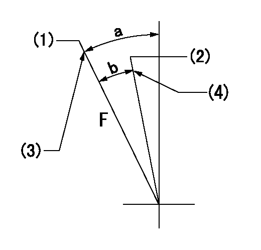
F:Full speed
(1)Set the pump speed at aa
(2)Set the pump speed at bb.
(3)Stopper bolt setting
(4)Stopper bolt setting
----------
aa=1275r/min bb=330r/min
----------
a=19.5deg+-5deg b=(11deg)+-5deg
----------
aa=1275r/min bb=330r/min
----------
a=19.5deg+-5deg b=(11deg)+-5deg
0000000901

F:Full load
I:Idle
(1)Stopper bolt setting
----------
----------
a=10deg+-5deg b=21deg+-3deg
----------
----------
a=10deg+-5deg b=21deg+-3deg
Stop lever angle
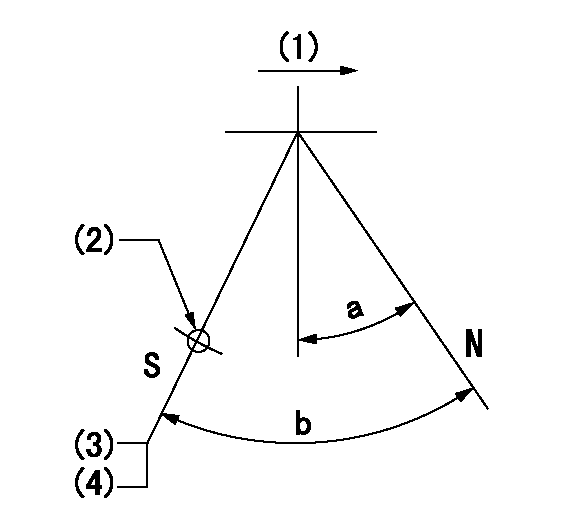
N:Pump normal
S:Stop the pump.
(1)Drive side
(1)Use the hole at R = aa
(3)Rack position bb
(4)Stopper bolt setting
----------
aa=36mm bb=3.7-0.5mm
----------
a=10.5deg+-5deg b=57deg+7deg-5deg
----------
aa=36mm bb=3.7-0.5mm
----------
a=10.5deg+-5deg b=57deg+7deg-5deg
0000001501 MICRO SWITCH
Adjustment of the micro-switch
Adjust the bolt to obtain the following lever position when the micro-switch is ON.
(1)Speed N1
(2)Rack position Ra
----------
N1=325r/min Ra=5.9+-0.1mm
----------
----------
N1=325r/min Ra=5.9+-0.1mm
----------
0000001601 GOVERNOR TORQUE CONTROL

Dr:Torque control stroke
(A): Without torque control spring capsule
1. Adjustment procedures
(1)Procedure is the same as that for the RFD (former type), except that the positive torque control stroke must be determined at the full lever setting.
2. Procedures for adjustment
(1)Remove the torque control spring capsule.
(2)Operate the pump at approximately N1. (End of idling spring operation < N1.)
(3)Tilt the lever to the full side.
(4)Set so that R = RF.
(5)Increase the speed by pushing in the screw (attached to the bracket on the rear of the tension lever) through the adjusting window.
(6)Adjust so that the torque control stroke Dr1 can be obtained.
(7)Align N2 and N3 with the torque control spring capsule.
3. Final confirmation
(1)After final confirmation, temporarily set the load lever to N = N1, R = idling position.
(2)From this condition, increase speed to N = N4.
(3)Confirm that positive torque control stroke is Dr2.
----------
N1=500r/min N2=(700)r/min N3=(940)r/min N4=1100r/min RF=10.2mm Dr1=0.9mm Dr2=0+0.3mm
----------
----------
N1=500r/min N2=(700)r/min N3=(940)r/min N4=1100r/min RF=10.2mm Dr1=0.9mm Dr2=0+0.3mm
----------
Timing setting

(1)Pump vertical direction
(2)Coupling's key groove position at No 1 cylinder's beginning of injection
(3)B.T.D.C.: aa
(4)-
----------
aa=12deg
----------
a=(40deg)
----------
aa=12deg
----------
a=(40deg)
Information:
Spray starting fluid only while cranking the engine.
1. Heat the glow plugs (If equipped) for the approximate heating time shown in the STARTING AID CHART. 2. Turn the HEAT-START switch to START position. While cranking, spray starting fluid into the air inlet or air cleaner for approximately 1 second.
Wait at least 2 seconds before spraying starting fluid again.
3. If necessary, repeat the procedure.4. After the engine starts, it may be necessary to return the HEAT-START switch to the HEAT position until the engine runs smoothly.Jacket Water Heater (Attachment)
In very low temperatures, the lubricating oil must be warmed to allow starting. A jacket water heater can maintain the water temperature at approximately 90°F (32°C). The warm water will keep the oil in the upper part of the engine block warm enough to flow when starting.Dipstick Oil Heater
Contact your Caterpillar dealer before installing a dipstick crankcase oil heater.
Generator
Starting Single Unit Operation
1. Make all preliminary engine starting checks.2. Be sure the main or line circuit breaker is open.3. Start the engine and allow it to warm up.4. Close the main circuit breaker.5. Apply the load. Do not try to apply full load in one move, rather apply the load in increments to maintain system frequency at a constant level.Standby Generator Sets
Most standby units are automatic. They start, pickup the load, run and stop without an operator in attendance. Standby units can not change the governor control setting automatically. The throttle must be preset for the proper operation of that unit. Whenever the set is exercised or operated manually, be sure the throttle setting is correct for automatic operation. Check all switches to see they are properly set: Start Selector Switch in AUTOMATIC position and any Emergency Stop Switches in RUN position.Paralleling
Units may be paralleled at no load or paralleled with units under load. To parallel two or more units the following conditions must be met:1. Same phase rotation.2. Same voltage level.3. Same voltage droop.4. Same frequency.5. Voltages must be in phase.The first condition is established by "phased" wiring connections of initial installation.The second and third conditions are usually established by semi-permanent adjustments to the generator controls.The fourth and fifth conditions are under control of the operation in manual paralleling systems (or under automatic control in automatic paralleling systems).To Parallel
1. Start the unit to be paralleled.2. Turn the synchronizer lights on.3. After the engine has run long enough to warm up, bring it up to synchronous speed (the same frequency as the unit on the line). The synchronizing lights will begin to blink.4. Using the governor control, adjust the speed until the lights blink very slowly.5. The lights are off when the voltages of the two units are in phase. At this point, very quickly close the breaker while the lights are out. The frequency of the incoming unit should be slightly greater than the line frequency. This will allow the incoming unit to assume some of the load rather than add to the system load.Load Division
Once two units have been paralleled,
Have questions with 106873-2662?
Group cross 106873-2662 ZEXEL
Mitsubishi
Mitsubishi
Mitsubishi
106873-2662
INJECTION-PUMP ASSEMBLY