Information injection-pump assembly
ZEXEL
106873-2560
1068732560
MITSUBISHI
ME160270
me160270

Rating:
Cross reference number
ZEXEL
106873-2560
1068732560
MITSUBISHI
ME160270
me160270
Zexel num
Bosch num
Firm num
Name
Calibration Data:
Adjustment conditions
Test oil
1404 Test oil ISO4113 or {SAEJ967d}
1404 Test oil ISO4113 or {SAEJ967d}
Test oil temperature
degC
40
40
45
Nozzle and nozzle holder
105780-8140
Bosch type code
EF8511/9A
Nozzle
105780-0000
Bosch type code
DN12SD12T
Nozzle holder
105780-2080
Bosch type code
EF8511/9
Opening pressure
MPa
17.2
Opening pressure
kgf/cm2
175
Injection pipe
Outer diameter - inner diameter - length (mm) mm 8-3-600
Outer diameter - inner diameter - length (mm) mm 8-3-600
Overflow valve
131424-4620
Overflow valve opening pressure
kPa
255
221
289
Overflow valve opening pressure
kgf/cm2
2.6
2.25
2.95
Tester oil delivery pressure
kPa
157
157
157
Tester oil delivery pressure
kgf/cm2
1.6
1.6
1.6
Direction of rotation (viewed from drive side)
Right R
Right R
Injection timing adjustment
Direction of rotation (viewed from drive side)
Right R
Right R
Injection order
1-2-7-3-
4-5-6-8
Pre-stroke
mm
4.8
4.75
4.85
Beginning of injection position
Governor side NO.1
Governor side NO.1
Difference between angles 1
Cyl.1-2 deg. 45 44.5 45.5
Cyl.1-2 deg. 45 44.5 45.5
Difference between angles 2
Cal 1-7 deg. 90 89.5 90.5
Cal 1-7 deg. 90 89.5 90.5
Difference between angles 3
Cal 1-3 deg. 135 134.5 135.5
Cal 1-3 deg. 135 134.5 135.5
Difference between angles 4
Cal 1-4 deg. 180 179.5 180.5
Cal 1-4 deg. 180 179.5 180.5
Difference between angles 5
Cal 1-5 deg. 225 224.5 225.5
Cal 1-5 deg. 225 224.5 225.5
Difference between angles 6
Cal 1-6 deg. 270 269.5 270.5
Cal 1-6 deg. 270 269.5 270.5
Difference between angles 7
Cal 1-8 deg. 315 314.5 315.5
Cal 1-8 deg. 315 314.5 315.5
Injection quantity adjustment
Adjusting point
-
Rack position
10.7
Pump speed
r/min
650
650
650
Each cylinder's injection qty
mm3/st.
148.6
144.1
153.1
Basic
*
Fixing the rack
*
Standard for adjustment of the maximum variation between cylinders
*
Injection quantity adjustment_02
Adjusting point
C
Rack position
6.8+-0.5
Pump speed
r/min
225
225
225
Each cylinder's injection qty
mm3/st.
19
16.1
21.9
Fixing the rack
*
Standard for adjustment of the maximum variation between cylinders
*
Injection quantity adjustment_03
Adjusting point
A
Rack position
R1(10.7)
Pump speed
r/min
650
650
650
Average injection quantity
mm3/st.
148.6
147.6
149.6
Fixing the lever
*
Injection quantity adjustment_04
Adjusting point
B
Rack position
R1-0.4
Pump speed
r/min
1100
1100
1100
Average injection quantity
mm3/st.
137
135
139
Fixing the lever
*
Injection quantity adjustment_05
Adjusting point
E
Rack position
-
Pump speed
r/min
100
100
100
Average injection quantity
mm3/st.
173
153
193
Fixing the lever
*
Remarks
After startup boost setting
After startup boost setting
Timer adjustment
Pump speed
r/min
860--
Advance angle
deg.
0
0
0
Remarks
Start
Start
Timer adjustment_02
Pump speed
r/min
810
Advance angle
deg.
0.5
Timer adjustment_03
Pump speed
r/min
1030
Advance angle
deg.
4.5
4
5
Remarks
Finish
Finish
Test data Ex:
Governor adjustment
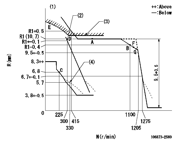
N:Pump speed
R:Rack position (mm)
(1)Tolerance for racks not indicated: +-0.05mm.
(2)When air cylinder is operating.
(3)Excess fuel setting for starting: SXL
(4)Damper spring setting
----------
SXL=10.9+-0.1mm
----------
----------
SXL=10.9+-0.1mm
----------
Speed control lever angle
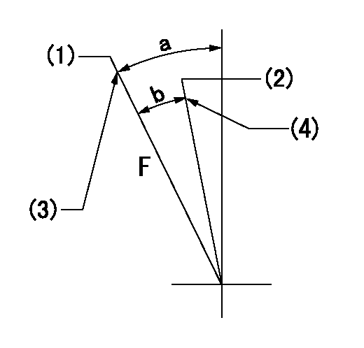
F:Full speed
(1)Set the pump speed at aa
(2)Set the pump speed at bb.
(3)Stopper bolt setting
(4)Stopper bolt setting
----------
aa=1275r/min bb=300r/min
----------
a=20.5deg+-5deg b=(10deg)+-5deg
----------
aa=1275r/min bb=300r/min
----------
a=20.5deg+-5deg b=(10deg)+-5deg
0000000901

F:Full load
I:Idle
(1)Stopper bolt setting
----------
----------
a=10deg+-5deg b=25.5deg+-3deg
----------
----------
a=10deg+-5deg b=25.5deg+-3deg
Stop lever angle
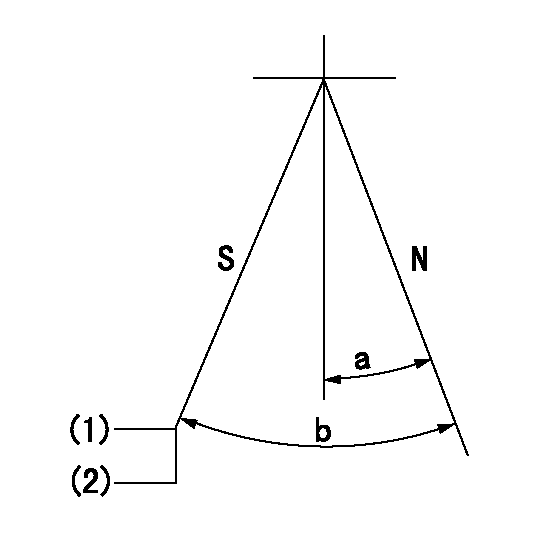
N:Pump normal
S:Stop the pump.
(1)Rack position = aa
(2)Stopper bolt setting
----------
aa=4.3-0.5mm
----------
a=10.5deg+-5deg b=55deg+7deg-5deg
----------
aa=4.3-0.5mm
----------
a=10.5deg+-5deg b=55deg+7deg-5deg
0000001501 MICRO SWITCH
Adjustment of the micro-switch
Adjust the bolt to obtain the following lever position when the micro-switch is ON.
(1)Speed N1
(2)Rack position Ra
----------
N1=325r/min Ra=6.3+-0.1mm
----------
----------
N1=325r/min Ra=6.3+-0.1mm
----------
Timing setting

(1)Pump vertical direction
(2)Coupling's key groove position at No 1 cylinder's beginning of injection
(3)B.T.D.C.: aa
(4)-
----------
aa=12deg
----------
a=(40deg)
----------
aa=12deg
----------
a=(40deg)
Information:
1. Remove oil supply tube (1) and suction bell and tube (2). 2. Remove bolts (3) that hold the oil pump to the cylinder block, and remove oil pump (4). The following steps are for installation of the oil pump.3. Put oil pump (4) in position on the cylinder block. Install the bolts that hold the oil pump to the cylinder block.4. Put clean engine oil on the O-ring seals of the tubes.5. Install oil supply tube (1) and suction bell and tube (2).End By:a. install oil panDisassemble Oil Pump
Start By:a. remove oil pump1. Remove the bolt and washer that hold the gear on the shaft. 2. Use tooling (A), and remove drive gear (1) from the shaft. Remove the key from the shaft. 3. Remove retainer (3) for the bypass valve.4. Remove the spring and bypass valve.5. Remove cover (2) from the pump body. 6. Use tooling (B), and remove the bearings from the cover. 7. Remove gears (5) and (6) from pump body (4).8. Use tooling (B), and remove the bearings from pump body (4).Assemble Oil Pump
1. Use tooling (B) to install the bearings in the pump body. Install the bearings so the joint in the bearings is 30 ° 15 ° from the center line of the oil pump outlet passage (7). 2. Install idler gear (5) and drive gear (6) in the oil pump body. Put clean engine oil on the bearings and the gears. 3. Use tooling (B), and install the bearings in cover (2). Install the bearings so the joint in the bearings is 30 ° 15 ° from the center line of the bearing bores toward oil pump outlet passage (7).4. Install bypass valve (8), spring (9) and the retainer.5. Install the key on the shaft. 6. Install gear (1) on the shaft. Install the washer and bolt that hold the gear on the shaft. Be sure the pump turns freely after assembly.End By:a. install oil pump