Information injection-pump assembly
ZEXEL
106873-2481
1068732481
MITSUBISHI
ME160282
me160282
Rating:
Service parts 106873-2481 INJECTION-PUMP ASSEMBLY:
1.
_
7.
COUPLING PLATE
8.
_
9.
_
11.
Nozzle and Holder
ME160284
12.
Open Pre:MPa(Kqf/cm2)
17.7{180}/21.6{220}
15.
NOZZLE SET
Include in #1:
106873-2481
as INJECTION-PUMP ASSEMBLY
Cross reference number
ZEXEL
106873-2481
1068732481
MITSUBISHI
ME160282
me160282
Zexel num
Bosch num
Firm num
Name
Calibration Data:
Adjustment conditions
Test oil
1404 Test oil ISO4113 or {SAEJ967d}
1404 Test oil ISO4113 or {SAEJ967d}
Test oil temperature
degC
40
40
45
Nozzle and nozzle holder
105780-8140
Bosch type code
EF8511/9A
Nozzle
105780-0000
Bosch type code
DN12SD12T
Nozzle holder
105780-2080
Bosch type code
EF8511/9
Opening pressure
MPa
17.2
Opening pressure
kgf/cm2
175
Injection pipe
Outer diameter - inner diameter - length (mm) mm 8-3-600
Outer diameter - inner diameter - length (mm) mm 8-3-600
Overflow valve
131424-4620
Overflow valve opening pressure
kPa
255
221
289
Overflow valve opening pressure
kgf/cm2
2.6
2.25
2.95
Tester oil delivery pressure
kPa
157
157
157
Tester oil delivery pressure
kgf/cm2
1.6
1.6
1.6
Direction of rotation (viewed from drive side)
Right R
Right R
Injection timing adjustment
Direction of rotation (viewed from drive side)
Right R
Right R
Injection order
1-2-7-3-
4-5-6-8
Pre-stroke
mm
4.8
4.75
4.85
Beginning of injection position
Governor side NO.1
Governor side NO.1
Difference between angles 1
Cyl.1-2 deg. 45 44.5 45.5
Cyl.1-2 deg. 45 44.5 45.5
Difference between angles 2
Cal 1-7 deg. 90 89.5 90.5
Cal 1-7 deg. 90 89.5 90.5
Difference between angles 3
Cal 1-3 deg. 135 134.5 135.5
Cal 1-3 deg. 135 134.5 135.5
Difference between angles 4
Cal 1-4 deg. 180 179.5 180.5
Cal 1-4 deg. 180 179.5 180.5
Difference between angles 5
Cal 1-5 deg. 225 224.5 225.5
Cal 1-5 deg. 225 224.5 225.5
Difference between angles 6
Cal 1-6 deg. 270 269.5 270.5
Cal 1-6 deg. 270 269.5 270.5
Difference between angles 7
Cal 1-8 deg. 315 314.5 315.5
Cal 1-8 deg. 315 314.5 315.5
Injection quantity adjustment
Adjusting point
-
Rack position
10.7
Pump speed
r/min
650
650
650
Each cylinder's injection qty
mm3/st.
148.6
144.1
153.1
Basic
*
Fixing the rack
*
Standard for adjustment of the maximum variation between cylinders
*
Injection quantity adjustment_02
Adjusting point
C
Rack position
6.8+-0.5
Pump speed
r/min
225
225
225
Each cylinder's injection qty
mm3/st.
19
16.1
21.9
Fixing the rack
*
Standard for adjustment of the maximum variation between cylinders
*
Injection quantity adjustment_03
Adjusting point
A
Rack position
R1(10.7)
Pump speed
r/min
650
650
650
Average injection quantity
mm3/st.
148.6
147.6
149.6
Fixing the lever
*
Injection quantity adjustment_04
Adjusting point
B
Rack position
R1-0.4
Pump speed
r/min
1100
1100
1100
Average injection quantity
mm3/st.
137
135
139
Fixing the lever
*
Injection quantity adjustment_05
Adjusting point
E
Rack position
-
Pump speed
r/min
100
100
100
Average injection quantity
mm3/st.
173
153
193
Fixing the lever
*
Remarks
After startup boost setting
After startup boost setting
Timer adjustment
Pump speed
r/min
860--
Advance angle
deg.
0
0
0
Remarks
Start
Start
Timer adjustment_02
Pump speed
r/min
810
Advance angle
deg.
0.5
Timer adjustment_03
Pump speed
r/min
1030
Advance angle
deg.
4.5
4
5
Remarks
Finish
Finish
Test data Ex:
Governor adjustment
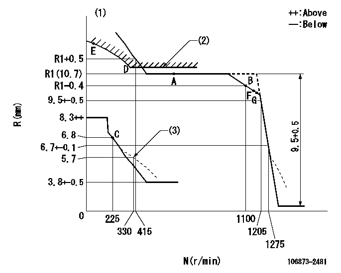
N:Pump speed
R:Rack position (mm)
(1)Tolerance for racks not indicated: +-0.05mm.
(2)Excess fuel setting for starting: SXL
(3)Damper spring setting
----------
SXL=10.9+-0.1mm
----------
----------
SXL=10.9+-0.1mm
----------
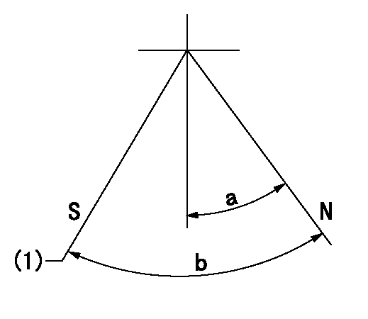
Speed control lever angle

F:Full speed
----------
----------
a=20.5deg+-5deg
----------
----------
a=20.5deg+-5deg
0000000901

F:Full load
I:Idle
(1)Stopper bolt setting
----------
----------
a=10deg+-5deg b=25.5deg+-3deg
----------
----------
a=10deg+-5deg b=25.5deg+-3deg
Stop lever angle
N:Pump normal
S:Stop the pump.
(1)Rack position = aa, stopper bolt setting
----------
aa=4.3-0.5mm
----------
a=10.5deg+-5deg b=55deg+7deg-5deg
----------
aa=4.3-0.5mm
----------
a=10.5deg+-5deg b=55deg+7deg-5deg
0000001501 MICRO SWITCH
Adjustment of the micro-switch
Adjust the bolt to obtain the following lever position when the micro-switch is ON.
(1)Speed N1
(2)Rack position Ra
----------
N1=325r/min Ra=6.3+-0.1mm
----------
----------
N1=325r/min Ra=6.3+-0.1mm
----------
Timing setting

(1)Pump vertical direction
(2)Coupling's key groove position at No 1 cylinder's beginning of injection
(3)B.T.D.C.: aa
(4)-
----------
aa=12deg
----------
a=(40deg)
----------
aa=12deg
----------
a=(40deg)
Information:
1. Disconnect fuel line (1) from the fuel transfer pump. Disconnect fuel line (2) from the fuel injection pump housing. Remove line (3) from the fuel ratio control and aftercooler housing. 2. Disconnect fuel injection lines (4) from the fuel injection pump housing.
Do not disconnect the air line from the air compressor governor until the air pressure is zero.
3. Loosen the bleed valves, and release the air pressure in the air tank. 4. Remove air line (5). Remove coolant line (6). 5. The weight of the fuel injection pump housing and governor is 57 kg (125 lb). Attach a hoist to the fuel injection pump housing, and remove bolts (7). 6. Remove the two nuts and two bolts (8) and bolt (9). Remove fuel injection pump housing and governor (10). 7. Remove O-ring seals (11) from the fuel injection pump housing.Install Fuel Injection Pump Housing And Governor
1. Attach a hoist to the fuel injection pump housing and governor (1). Be sure that the three O-ring seals are in position in the fuel injection pump housing. Install the fuel injection pump housing and governor on the timing gear housing. 2. Connect air line (2) and water line (3) to the air compressor. 3. Connect fuel injection lines (4) to fuel injection pump housing, and tighten the fuel injection line nuts to a torque of 40 7 N m (30 5 lb ft) with tool (C). 4. Connect fuel line (5) to fuel injection pump housing, and connect fuel line (6) to the fuel transfer pump. Install line (7) between the fuel ratio control and aftercooler housing. For timing of the fuel injection pump, see Install Automatic Timing Advance.End By:a. install automatic timing advance