Information injection-pump assembly
BOSCH
F 01G 09U 0AV
f01g09u0av
ZEXEL
106873-2370
1068732370
Rating:
Cross reference number
BOSCH
F 01G 09U 0AV
f01g09u0av
ZEXEL
106873-2370
1068732370
Zexel num
Bosch num
Firm num
Name
Calibration Data:
Adjustment conditions
Test oil
1404 Test oil ISO4113 or {SAEJ967d}
1404 Test oil ISO4113 or {SAEJ967d}
Test oil temperature
degC
40
40
45
Nozzle and nozzle holder
105780-8140
Bosch type code
EF8511/9A
Nozzle
105780-0000
Bosch type code
DN12SD12T
Nozzle holder
105780-2080
Bosch type code
EF8511/9
Opening pressure
MPa
17.2
Opening pressure
kgf/cm2
175
Injection pipe
Outer diameter - inner diameter - length (mm) mm 8-3-600
Outer diameter - inner diameter - length (mm) mm 8-3-600
Overflow valve
131424-4620
Overflow valve opening pressure
kPa
255
221
289
Overflow valve opening pressure
kgf/cm2
2.6
2.25
2.95
Tester oil delivery pressure
kPa
157
157
157
Tester oil delivery pressure
kgf/cm2
1.6
1.6
1.6
Direction of rotation (viewed from drive side)
Right R
Right R
Injection timing adjustment
Direction of rotation (viewed from drive side)
Right R
Right R
Injection order
1-2-7-3-
4-5-6-8
Pre-stroke
mm
4.8
4.75
4.85
Beginning of injection position
Governor side NO.1
Governor side NO.1
Difference between angles 1
Cyl.1-2 deg. 45 44.5 45.5
Cyl.1-2 deg. 45 44.5 45.5
Difference between angles 2
Cal 1-7 deg. 90 89.5 90.5
Cal 1-7 deg. 90 89.5 90.5
Difference between angles 3
Cal 1-3 deg. 135 134.5 135.5
Cal 1-3 deg. 135 134.5 135.5
Difference between angles 4
Cal 1-4 deg. 180 179.5 180.5
Cal 1-4 deg. 180 179.5 180.5
Difference between angles 5
Cal 1-5 deg. 225 224.5 225.5
Cal 1-5 deg. 225 224.5 225.5
Difference between angles 6
Cal 1-6 deg. 270 269.5 270.5
Cal 1-6 deg. 270 269.5 270.5
Difference between angles 7
Cal 1-8 deg. 315 314.5 315.5
Cal 1-8 deg. 315 314.5 315.5
Injection quantity adjustment
Adjusting point
-
Rack position
10.6
Pump speed
r/min
700
700
700
Each cylinder's injection qty
mm3/st.
134.6
130.6
138.6
Basic
*
Fixing the rack
*
Standard for adjustment of the maximum variation between cylinders
*
Injection quantity adjustment_02
Adjusting point
C
Rack position
5.9+-0.5
Pump speed
r/min
225
225
225
Each cylinder's injection qty
mm3/st.
15.8
13.4
18.2
Fixing the rack
*
Standard for adjustment of the maximum variation between cylinders
*
Injection quantity adjustment_03
Adjusting point
A
Rack position
R1(10.6)
Pump speed
r/min
700
700
700
Average injection quantity
mm3/st.
134.6
133.6
135.6
Basic
*
Fixing the lever
*
Boost pressure
kPa
28
28
Boost pressure
mmHg
210
210
Injection quantity adjustment_04
Adjusting point
B
Rack position
R1-0.15
Pump speed
r/min
1100
1100
1100
Average injection quantity
mm3/st.
138.8
134.8
142.8
Fixing the lever
*
Boost pressure
kPa
28
28
Boost pressure
mmHg
210
210
Injection quantity adjustment_05
Adjusting point
D
Rack position
-
Pump speed
r/min
200
200
200
Average injection quantity
mm3/st.
100
60
140
Fixing the lever
*
Boost pressure
kPa
0
0
0
Boost pressure
mmHg
0
0
0
Injection quantity adjustment_06
Adjusting point
E
Rack position
R1+0.35
Pump speed
r/min
500
500
500
Average injection quantity
mm3/st.
142.8
139.8
145.8
Fixing the lever
*
Boost pressure
kPa
28
28
Boost pressure
mmHg
210
210
Injection quantity adjustment_07
Adjusting point
F
Rack position
R1-0.9
Pump speed
r/min
700
700
700
Average injection quantity
mm3/st.
116.8
114.8
118.8
Fixing the lever
*
Boost pressure
kPa
0
0
0
Boost pressure
mmHg
0
0
0
Injection quantity adjustment_08
Adjusting point
G
Rack position
12+-0.1
Pump speed
r/min
200
200
200
Average injection quantity
mm3/st.
135
125
145
Fixing the lever
*
Boost pressure
kPa
28
28
Boost pressure
mmHg
210
210
Rack limit
*
Boost compensator adjustment
Pump speed
r/min
450
450
450
Rack position
R1-0.9
Boost pressure
kPa
3.3
3.3
5.3
Boost pressure
mmHg
25
25
40
Boost compensator adjustment_02
Pump speed
r/min
450
450
450
Rack position
R1(10.6)
Boost pressure
kPa
10
8.7
11.3
Boost pressure
mmHg
75
65
85
Boost compensator adjustment_03
Pump speed
r/min
450
450
450
Rack position
(11.4)
Boost pressure
kPa
14.7
14.7
14.7
Boost pressure
mmHg
110
110
110
Timer adjustment
Pump speed
r/min
900--
Advance angle
deg.
0
0
0
Remarks
Start
Start
Timer adjustment_02
Pump speed
r/min
850
Advance angle
deg.
0.5
Timer adjustment_03
Pump speed
r/min
1100
Advance angle
deg.
4.5
4
5
Remarks
Finish
Finish
Test data Ex:
Governor adjustment
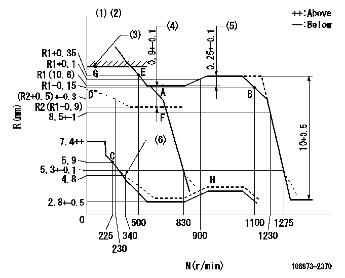
N:Pump speed
R:Rack position (mm)
(1)Tolerance for racks not indicated: +-0.05mm.
(2)Boost compensator cancel stroke: BSL
(3)RACK LIMIT: RAL
(4)Boost compensator stroke
(5)Rack difference between N = N1 and N = N2
(6)Damper spring setting
----------
BSL=1.4mm RAL=12+-0.1mm N1=990r/min N2=700r/min
----------
----------
BSL=1.4mm RAL=12+-0.1mm N1=990r/min N2=700r/min
----------
Speed control lever angle
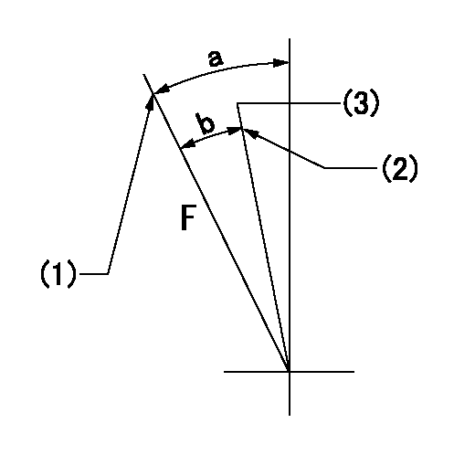
F:Full speed
(1)Stopper bolt setting
(2)Stopper bolt setting
(3)Set the pump speed at aa
----------
aa=830r/min
----------
a=16deg+-5deg b=(9deg)+-5deg
----------
aa=830r/min
----------
a=16deg+-5deg b=(9deg)+-5deg
0000000901
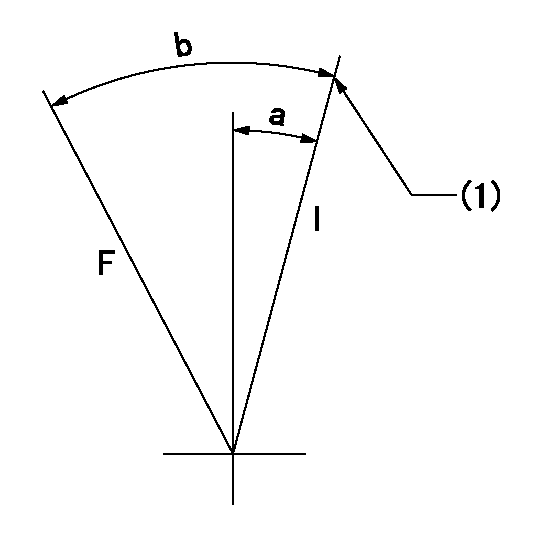
F:Full load
I:Idle
(1)Stopper bolt setting
----------
----------
a=10deg+-5deg b=29.5deg+-3deg
----------
----------
a=10deg+-5deg b=29.5deg+-3deg
Stop lever angle

S:Stop the pump.
(1)Rack position = aa
(2)Stopper bolt setting
(3)Free (at delivery)
----------
aa=3.3-0.5mm
----------
a=10.5deg+-5deg b=58deg+7deg-5deg
----------
aa=3.3-0.5mm
----------
a=10.5deg+-5deg b=58deg+7deg-5deg
0000001501 MICRO SWITCH
Adjustment of the micro-switch
Adjust the bolt to obtain the following lever position when the micro-switch is ON.
(1)Speed N1
(2)Rack position Ra
----------
N1=325r/min Ra=5.6+-0.1mm
----------
----------
N1=325r/min Ra=5.6+-0.1mm
----------
0000001601 2-STAGE CHANGEOVER DEVICE

RFD governor 2 stage changeover mechanism adjustment outline
(A) Bolt
(B) bolt
(c) Nut
(D) Return spring
(E) Bolt
(F) Bolt
(G) Screw
(H) Bolt
(I) Load lever
(J) Speed lever
(K) Air cylinder
(M Air inlet
Figure 1 is only for reference. Lever shape, etc, may vary.
1. Minimum-maximum speed specification adjustment (when running)
(a) Without applying air to the air cylinder, loosen bolts (A) and (B).
(1)High speed return L setting
(a) In the speed range Nf~Nf - 300r/min, adjust using the speed adjusting bolt to determine the temporary beginning of high speed control speed.
(b) Determine the rack position in the vicinity of Rf using the full load lever.
(c) Increase speed and confirm return distance L.
(d) Adjust using the tension lever bolt to obtain L.
(2)Setting full load rack position Rf
(a) Move the load control lever to the full side.
(b) Adjust the full load adjusting bolt so that Rf can be obtained, then fix.
(3)Setting the beginning of high speed operation Nf
(a) Adjust using bolt (E) so that Nf can be obtained, and then fix.
(4)Idle control setting (Re, Ni, Rc)
(a) Set the speed at Ns + 200r/min and move the load control lever to the idle side.
(b) Fix the lever in the position where Re can be obtained.
(c) Next, decrease speed to Ni and screw in the idle spring.
(d) Adjust to obtain rack position Ri.
(e) Increase the speed and after confirming that the rack position is Re at Ns, set the speed at 0.
(f) Confirm protrusion position Rc at idle.
(5)Damper spring adjustment
(a) Increase speed and set the speed at the rack position Rd - 0.1 mm
(b) Set using the damper spring so that the rack position Rd can be obtained.
(c) When Rd is not specified, Rd = Ri - 0.5 mm.
(6)High speed droop confirmation
(a) Return the load control lever to the full load lever position.
(b) Increase the speed and confirm that Rf can be obtained at Nf r/min.
(c) Confirm that speed is Nh at rack position Rh.
2. Variable speed specification adjustment (at operation)
(a) Remove return spring (D).
(b) Apply air pressure of 245~294 kPa {2.5~3 kg/cm2} to the air cylinder.
(c) Perform the following adjustment in this condition.
(1)Setting full load rack position Rf'
(a) Pull the load lever to the idle side.
(b) Obtain rack position Rf' using the nut (C). (Pump speed is Nf'-50 r/min.)
(2)Setting full speed Nf'
(a) Adjust using bolt (B) so that Nf can be obtained, and then fix.
(3)Low speed side setting
(a) At 350r/min, set bolt (F) at beginning of governor operation position, then fix.
3. Bolt (A) adjustment
(1)Install return spring (D) and perform the adjustments below at air pressure 0.
(a) Set at speed Nf using bolt (E).
(b) Screw in bolt (A).
(c) Screw in 1 more turn from the speed lever contact position
(d) Fix bolt (A).
(e) At this time confirm that the air cylinder's shaft moves approximately 1 mm towards the governor.
4. Lever operation confirmation using the air cylinder
(1)Apply 588 kPa {6 kg/cm2} air pressure to the air cylinder.
(2)Confirm that the cylinder piston is moved 50 mm by the spring (D).
----------
----------
----------
----------
Timing setting

(1)Pump vertical direction
(2)Coupling's key groove position at No 1 cylinder's beginning of injection
(3)-
(4)-
----------
----------
a=(40deg)
----------
----------
a=(40deg)
Information:
Fuel consumption complaints are related to engine owners expectations. They may often times be related to the engine itself, causes other than the engine, and in some cases the fuel consumption may be normal for the application. Only a good discussion with the owner/operator, as described in the "Owner/Operator Input" section, will give guidance as to a correct repair or to prevent unnecessary repairs.Owner/Operator Input
The following are some of the questions which should be asked before beginning any diagnosis or repair for an engine performance complaint. There Are No Hard And Fast Answers For These Questions. There are many factors that can cause poor fuel mileage or make users believe they are getting fuel-poor-mileage.There are also a variety of customer expectations which are acceptable. The answers to these questions will give you a better understanding and perspective on the complaint and may identify characteristics which will help pinpoint the cause of the complaint quickly.1. Are miles measured accurately? A most common problem in determining mpg is errors in recording the number of miles traveled.A. Is this vehicle hub or cab odometer accurate? The easiest way to check an odometer is to install a hub odometer known to be accurate and for the tire size on the truck. Run the truck over several hundred miles and compare the reading with the original odometer.Odometers may also be checked by comparing them to interstate mile posts or by running over a course of known length - a 50-mile run is required to get a good check.B. Are "book miles" or "driver-paid miles" correct? Another way in which miles for mpg calculations are obtained by a fleet is the use of "book miles" or "driver-paid miles". The use of this system can short mileage accumulation by 10 to 15%; thus, mpg is low by 10 to 15%.C. Is the vehicle used for pick-up and delivery operation? Another problem affecting mileage accumulation in many fleets is the use of linehaul equipment for pickup and delivery operations. In the "book mile" system, the truck rarely gets credit for any miles run in pick-up and delivery.2. Is fuel measurement accurate? There are a number of ways in which fuel measurement can be the source of mpg problems.A. Are fuel pumps calibrated? If fuel tickets come from company-owned fuel pumps, there can be errors because nonrevenue fuel pumps do not have calibration requirements in many states.B. Are road fuel tickets accurate? The only way to verify fuel additions when road fuel tickets are used is a laborious ticket-by-ticket audit ensuring that the correct amount of fuel has been entered for the vehicles in question and that there are no indications of incorrect entries.C. Are tank-full mileage checks correctly done? The big problem in "tank-full" checks is getting the tank filled to the same level before and after the user "checked the mileage". With two 100 gallon tanks, errors of 5 to 10 gallons are very common in topping off tanks because of the way truck tanks
The following are some of the questions which should be asked before beginning any diagnosis or repair for an engine performance complaint. There Are No Hard And Fast Answers For These Questions. There are many factors that can cause poor fuel mileage or make users believe they are getting fuel-poor-mileage.There are also a variety of customer expectations which are acceptable. The answers to these questions will give you a better understanding and perspective on the complaint and may identify characteristics which will help pinpoint the cause of the complaint quickly.1. Are miles measured accurately? A most common problem in determining mpg is errors in recording the number of miles traveled.A. Is this vehicle hub or cab odometer accurate? The easiest way to check an odometer is to install a hub odometer known to be accurate and for the tire size on the truck. Run the truck over several hundred miles and compare the reading with the original odometer.Odometers may also be checked by comparing them to interstate mile posts or by running over a course of known length - a 50-mile run is required to get a good check.B. Are "book miles" or "driver-paid miles" correct? Another way in which miles for mpg calculations are obtained by a fleet is the use of "book miles" or "driver-paid miles". The use of this system can short mileage accumulation by 10 to 15%; thus, mpg is low by 10 to 15%.C. Is the vehicle used for pick-up and delivery operation? Another problem affecting mileage accumulation in many fleets is the use of linehaul equipment for pickup and delivery operations. In the "book mile" system, the truck rarely gets credit for any miles run in pick-up and delivery.2. Is fuel measurement accurate? There are a number of ways in which fuel measurement can be the source of mpg problems.A. Are fuel pumps calibrated? If fuel tickets come from company-owned fuel pumps, there can be errors because nonrevenue fuel pumps do not have calibration requirements in many states.B. Are road fuel tickets accurate? The only way to verify fuel additions when road fuel tickets are used is a laborious ticket-by-ticket audit ensuring that the correct amount of fuel has been entered for the vehicles in question and that there are no indications of incorrect entries.C. Are tank-full mileage checks correctly done? The big problem in "tank-full" checks is getting the tank filled to the same level before and after the user "checked the mileage". With two 100 gallon tanks, errors of 5 to 10 gallons are very common in topping off tanks because of the way truck tanks