Information injection-pump assembly
ZEXEL
106873-2340
1068732340

Rating:
Cross reference number
ZEXEL
106873-2340
1068732340
Zexel num
Bosch num
Firm num
Name
106873-2340
INJECTION-PUMP ASSEMBLY
Calibration Data:
Adjustment conditions
Test oil
1404 Test oil ISO4113 or {SAEJ967d}
1404 Test oil ISO4113 or {SAEJ967d}
Test oil temperature
degC
40
40
45
Nozzle and nozzle holder
105780-8140
Bosch type code
EF8511/9A
Nozzle
105780-0000
Bosch type code
DN12SD12T
Nozzle holder
105780-2080
Bosch type code
EF8511/9
Opening pressure
MPa
17.2
Opening pressure
kgf/cm2
175
Injection pipe
Outer diameter - inner diameter - length (mm) mm 8-3-600
Outer diameter - inner diameter - length (mm) mm 8-3-600
Overflow valve
131424-4620
Overflow valve opening pressure
kPa
255
221
289
Overflow valve opening pressure
kgf/cm2
2.6
2.25
2.95
Tester oil delivery pressure
kPa
157
157
157
Tester oil delivery pressure
kgf/cm2
1.6
1.6
1.6
Direction of rotation (viewed from drive side)
Right R
Right R
Injection timing adjustment
Direction of rotation (viewed from drive side)
Right R
Right R
Injection order
1-2-7-3-
4-5-6-8
Pre-stroke
mm
4.8
4.75
4.85
Beginning of injection position
Governor side NO.1
Governor side NO.1
Difference between angles 1
Cyl.1-2 deg. 45 44.5 45.5
Cyl.1-2 deg. 45 44.5 45.5
Difference between angles 2
Cal 1-7 deg. 90 89.5 90.5
Cal 1-7 deg. 90 89.5 90.5
Difference between angles 3
Cal 1-3 deg. 135 134.5 135.5
Cal 1-3 deg. 135 134.5 135.5
Difference between angles 4
Cal 1-4 deg. 180 179.5 180.5
Cal 1-4 deg. 180 179.5 180.5
Difference between angles 5
Cal 1-5 deg. 225 224.5 225.5
Cal 1-5 deg. 225 224.5 225.5
Difference between angles 6
Cal 1-6 deg. 270 269.5 270.5
Cal 1-6 deg. 270 269.5 270.5
Difference between angles 7
Cal 1-8 deg. 315 314.5 315.5
Cal 1-8 deg. 315 314.5 315.5
Injection quantity adjustment
Adjusting point
-
Rack position
11.2
Pump speed
r/min
700
700
700
Each cylinder's injection qty
mm3/st.
148.5
144
153
Basic
*
Fixing the rack
*
Standard for adjustment of the maximum variation between cylinders
*
Injection quantity adjustment_02
Adjusting point
C
Rack position
5.9+-0.5
Pump speed
r/min
225
225
225
Each cylinder's injection qty
mm3/st.
15.8
13.4
18.2
Fixing the rack
*
Standard for adjustment of the maximum variation between cylinders
*
Injection quantity adjustment_03
Adjusting point
A
Rack position
R1(11.2)
Pump speed
r/min
700
700
700
Average injection quantity
mm3/st.
148.5
147.5
149.5
Basic
*
Fixing the lever
*
Boost pressure
kPa
26.7
26.7
Boost pressure
mmHg
200
200
Injection quantity adjustment_04
Adjusting point
B
Rack position
R1+0.05
Pump speed
r/min
1100
1100
1100
Average injection quantity
mm3/st.
157.8
153.8
161.8
Fixing the lever
*
Boost pressure
kPa
26.7
26.7
Boost pressure
mmHg
200
200
Boost compensator adjustment
Pump speed
r/min
650
650
650
Rack position
R1-1.25
Boost pressure
kPa
3.3
3.3
5.3
Boost pressure
mmHg
25
25
40
Boost compensator adjustment_02
Pump speed
r/min
650
650
650
Rack position
R1-0.7
Boost pressure
kPa
8
6.7
9.3
Boost pressure
mmHg
60
50
70
Boost compensator adjustment_03
Pump speed
r/min
650
650
650
Rack position
R1(11.2)
Boost pressure
kPa
13.3
6.6
20
Boost pressure
mmHg
100
50
150
Timer adjustment
Pump speed
r/min
900--
Advance angle
deg.
0
0
0
Remarks
Start
Start
Timer adjustment_02
Pump speed
r/min
850
Advance angle
deg.
0.5
Timer adjustment_03
Pump speed
r/min
1100
Advance angle
deg.
4
3.5
4.5
Remarks
Finish
Finish
Test data Ex:
Governor adjustment
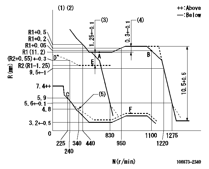
N:Pump speed
R:Rack position (mm)
(1)Tolerance for racks not indicated: +-0.05mm.
(2)Boost compensator cancel stroke: BSL
(3)Boost compensator stroke
(4)Rack difference between N = N1 and N = N2
(5)Damper spring setting
----------
BSL=1.6mm N1=1020r/min N2=700r/min
----------
----------
BSL=1.6mm N1=1020r/min N2=700r/min
----------
Speed control lever angle
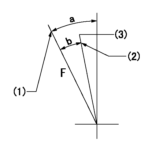
F:Full speed
(1)Stopper bolt setting
(2)Stopper bolt setting
(3)Set the pump speed at aa
----------
aa=830r/min
----------
a=16deg+-5deg b=(9.5deg)+-5deg
----------
aa=830r/min
----------
a=16deg+-5deg b=(9.5deg)+-5deg
0000000901
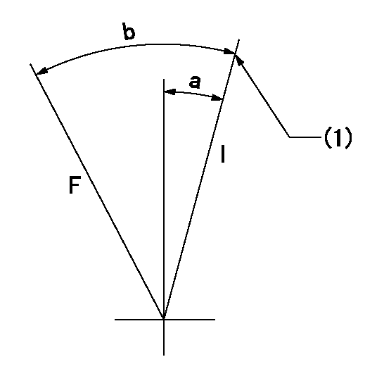
F:Full load
I:Idle
(1)Stopper bolt setting
----------
----------
a=10deg+-5deg b=29.5deg+-3deg
----------
----------
a=10deg+-5deg b=29.5deg+-3deg
Stop lever angle

S:Stop the pump.
(1)Rack position = aa
(2)Stopper bolt setting
(3)Free (at delivery)
----------
aa=3.3-0.5mm
----------
a=10.5deg+-5deg b=58deg+7deg-5deg
----------
aa=3.3-0.5mm
----------
a=10.5deg+-5deg b=58deg+7deg-5deg
0000001501 MICRO SWITCH
Adjustment of the micro-switch
Adjust the bolt to obtain the following lever position when the micro-switch is ON.
(1)Speed N1
(2)Rack position Ra
----------
N1=325r/min Ra=5.4+-0.1mm
----------
----------
N1=325r/min Ra=5.4+-0.1mm
----------
0000001601 2-STAGE CHANGEOVER DEVICE

RFD governor 2 stage changeover mechanism adjustment outline
(A) Bolt
(B) bolt
(c) Nut
(D) Return spring
(E) Bolt
(F) Bolt
(G) Screw
(H) Bolt
(I) Load lever
(J) Speed lever
(K) Air cylinder
(M Air inlet
Figure 1 is only for reference. Lever shape, etc, may vary.
1. Minimum-maximum speed specification adjustment (when running)
(a) Without applying air to the air cylinder, loosen bolts (A) and (B).
(1)High speed return L setting
(a) In the speed range Nf~Nf - 300r/min, adjust using the speed adjusting bolt to determine the temporary beginning of high speed control speed.
(b) Determine the rack position in the vicinity of Rf using the full load lever.
(c) Increase speed and confirm return distance L.
(d) Adjust using the tension lever bolt to obtain L.
(2)Setting full load rack position Rf
(a) Move the load control lever to the full side.
(b) Adjust the full load adjusting bolt so that Rf can be obtained, then fix.
(3)Setting the beginning of high speed operation Nf
(a) Adjust using bolt (E) so that Nf can be obtained, and then fix.
(4)Idle control setting (Re, Ni, Rc)
(a) Set the speed at Ns + 200r/min and move the load control lever to the idle side.
(b) Fix the lever in the position where Re can be obtained.
(c) Next, decrease speed to Ni and screw in the idle spring.
(d) Adjust to obtain rack position Ri.
(e) Increase the speed and after confirming that the rack position is Re at Ns, set the speed at 0.
(f) Confirm protrusion position Rc at idle.
(5)Damper spring adjustment
(a) Increase speed and set the speed at the rack position Rd - 0.1 mm
(b) Set using the damper spring so that the rack position Rd can be obtained.
(c) When Rd is not specified, Rd = Ri - 0.5 mm.
(6)High speed droop confirmation
(a) Return the load control lever to the full load lever position.
(b) Increase the speed and confirm that Rf can be obtained at Nf r/min.
(c) Confirm that speed is Nh at rack position Rh.
2. Variable speed specification adjustment (at operation)
(a) Remove return spring (D).
(b) Apply air pressure of 245~294 kPa {2.5~3 kg/cm2} to the air cylinder.
(c) Perform the following adjustment in this condition.
(1)Setting full load rack position Rf'
(a) Pull the load lever to the idle side.
(b) Obtain rack position Rf' using the nut (C). (Pump speed is Nf'-50 r/min.)
(2)Setting full speed Nf'
(a) Adjust using bolt (B) so that Nf can be obtained, and then fix.
(3)Low speed side setting
(a) At 350r/min, set bolt (F) at beginning of governor operation position, then fix.
3. Bolt (A) adjustment
(1)Install return spring (D) and perform the adjustments below at air pressure 0.
(a) Set at speed Nf using bolt (E).
(b) Screw in bolt (A).
(c) Screw in 1 more turn from the speed lever contact position
(d) Fix bolt (A).
(e) At this time confirm that the air cylinder's shaft moves approximately 1 mm towards the governor.
4. Lever operation confirmation using the air cylinder
(1)Apply 588 kPa {6 kg/cm2} air pressure to the air cylinder.
(2)Confirm that the cylinder piston is moved 50 mm by the spring (D).
----------
----------
----------
----------
Timing setting

(1)Pump vertical direction
(2)Coupling's key groove position at No 1 cylinder's beginning of injection
(3)-
(4)-
----------
----------
a=(40deg)
----------
----------
a=(40deg)
Information:
(1) Thickness of spacer plate ... 8.585 0.025 mm (.3379 .0009 in)Thickness of gasket that is placed between spacer plate and cylinder block ... 0.208 0.025 mm (.0081 .0009 in)Height of liner over spacer plate, under installation pressure ... 0.13 0.08 mm (.005 .003 in)(2) Height of four dowels above top surface of cylinder block:End dowels (Put 7M7456 Bearing Mount Compound on two end dowels at installation) ... 18.5 0.5 mm (.73 .02 in)Middle dowels ... 16.0 0.5 mm (.63 .02 in)(3) Dimension (new) from centerline of crankshaft bearing bore to top of block (top deck) ... 425.45 0.15 mm (16.750 .006 in)Minimum dimension from centerline of crankshaft bearing bore to top of block (top deck) ... 425.02 mm (16.733 in) The flatness across the whole contact surface of the block must be within 0.10 mm (.004 in) and within 0.05 mm (.002 in) for any 177 mm (7.0 in) section of the surface. The surface finish specification is 3.2 micrometers (125 micro-inches) maximum.(4) Bore in block for camshaft bearings ... 76.835 0.018 mm (3.0250 .0007 in) Install bearings with the oil holes in the bearings on the horizontal centerline. Make sure the bearing joint position is above the oil holes.(5) Bore in the block for the main bearings: Standard, original size (new) ... 129.891 0.013 mm (5.1138 .0005 in)0.64 mm (.025 in) larger than original size ... 130.526 0.013 mm (5.1388 .0005 in)(6) Distance from front of rear face of cylinder block to end of dowels ... 19.1 0.05 mm (.75 .02 in)(7) Width of main bearing cap ... 215.900 0.013 mm (8.5000 .0005 in)Width of block for main bearing cap ... 215.900 0.013 mm (8.5000 .0005 in)Clearance between main bearing cap and cylinder block ... 0.025 mm (.0009 in) tight to 0.025 mm (.0009 in) loose
Tightening Procedure For Main Bearings(8) Torque for the bolts that hold the caps for the main bearings: Install the main bearing caps with the marks (arrow) toward the front of the engine. Install each cap in the correct position by putting the number stamped on the bottom of the cap toward the corresponding number cast on left side of the cylinder block at the pan rail.a. Put 2P2506 Thread Lubricant on the threads of the bolts.b. Tighten the bolts first on the bearing tab side of the cap to ... 260 14 N m (190 10 lb ft)c. Tighten the bolts on the opposite side to ... 260 14 N m (190 10 lb ft)d. Put a mark on each bolt and cap.e. Tighten the bolts on the opposite side, from the mark ... 120 5°f. Tighten the bolts on the bearing tab side of the cap, from the mark ... 120 5°(9) Dimension (new) from centerline of crankshaft bearing bore to bottom of block (pan rails) ... 165.10 0.10
Tightening Procedure For Main Bearings(8) Torque for the bolts that hold the caps for the main bearings: Install the main bearing caps with the marks (arrow) toward the front of the engine. Install each cap in the correct position by putting the number stamped on the bottom of the cap toward the corresponding number cast on left side of the cylinder block at the pan rail.a. Put 2P2506 Thread Lubricant on the threads of the bolts.b. Tighten the bolts first on the bearing tab side of the cap to ... 260 14 N m (190 10 lb ft)c. Tighten the bolts on the opposite side to ... 260 14 N m (190 10 lb ft)d. Put a mark on each bolt and cap.e. Tighten the bolts on the opposite side, from the mark ... 120 5°f. Tighten the bolts on the bearing tab side of the cap, from the mark ... 120 5°(9) Dimension (new) from centerline of crankshaft bearing bore to bottom of block (pan rails) ... 165.10 0.10
Have questions with 106873-2340?
Group cross 106873-2340 ZEXEL
Mitsubishi
Mitsubishi
106873-2340
INJECTION-PUMP ASSEMBLY