Information injection-pump assembly
BOSCH
9 400 618 345
9400618345
ZEXEL
106873-2221
1068732221
MITSUBISHI
ME091689
me091689

Rating:
Service parts 106873-2221 INJECTION-PUMP ASSEMBLY:
1.
_
7.
COUPLING PLATE
8.
_
9.
_
11.
Nozzle and Holder
ME060110
12.
Open Pre:MPa(Kqf/cm2)
17.7{180}/21.6{220}
15.
NOZZLE SET
Include in #1:
106873-2221
as INJECTION-PUMP ASSEMBLY
Cross reference number
BOSCH
9 400 618 345
9400618345
ZEXEL
106873-2221
1068732221
MITSUBISHI
ME091689
me091689
Zexel num
Bosch num
Firm num
Name
106873-2221
9 400 618 345
ME091689 MITSUBISHI
INJECTION-PUMP ASSEMBLY
8DC11 * K
8DC11 * K
Calibration Data:
Adjustment conditions
Test oil
1404 Test oil ISO4113 or {SAEJ967d}
1404 Test oil ISO4113 or {SAEJ967d}
Test oil temperature
degC
40
40
45
Nozzle and nozzle holder
105780-8140
Bosch type code
EF8511/9A
Nozzle
105780-0000
Bosch type code
DN12SD12T
Nozzle holder
105780-2080
Bosch type code
EF8511/9
Opening pressure
MPa
17.2
Opening pressure
kgf/cm2
175
Injection pipe
Outer diameter - inner diameter - length (mm) mm 8-3-600
Outer diameter - inner diameter - length (mm) mm 8-3-600
Overflow valve
132424-0620
Overflow valve opening pressure
kPa
157
123
191
Overflow valve opening pressure
kgf/cm2
1.6
1.25
1.95
Tester oil delivery pressure
kPa
157
157
157
Tester oil delivery pressure
kgf/cm2
1.6
1.6
1.6
Direction of rotation (viewed from drive side)
Right R
Right R
Injection timing adjustment
Direction of rotation (viewed from drive side)
Right R
Right R
Injection order
1-2-7-3-
4-5-6-8
Pre-stroke
mm
4.8
4.75
4.85
Beginning of injection position
Governor side NO.1
Governor side NO.1
Difference between angles 1
Cyl.1-2 deg. 45 44.5 45.5
Cyl.1-2 deg. 45 44.5 45.5
Difference between angles 2
Cal 1-7 deg. 90 89.5 90.5
Cal 1-7 deg. 90 89.5 90.5
Difference between angles 3
Cal 1-3 deg. 135 134.5 135.5
Cal 1-3 deg. 135 134.5 135.5
Difference between angles 4
Cal 1-4 deg. 180 179.5 180.5
Cal 1-4 deg. 180 179.5 180.5
Difference between angles 5
Cal 1-5 deg. 225 224.5 225.5
Cal 1-5 deg. 225 224.5 225.5
Difference between angles 6
Cal 1-6 deg. 270 269.5 270.5
Cal 1-6 deg. 270 269.5 270.5
Difference between angles 7
Cal 1-8 deg. 315 314.5 315.5
Cal 1-8 deg. 315 314.5 315.5
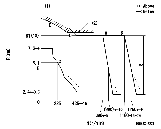
Injection quantity adjustment
Adjusting point
-
Rack position
10
Pump speed
r/min
700
700
700
Each cylinder's injection qty
mm3/st.
129
125.1
132.9
Basic
*
Fixing the rack
*
Standard for adjustment of the maximum variation between cylinders
*
Injection quantity adjustment_02
Adjusting point
C
Rack position
6.1+-0.5
Pump speed
r/min
225
225
225
Each cylinder's injection qty
mm3/st.
20
17
23
Fixing the rack
*
Standard for adjustment of the maximum variation between cylinders
*
Injection quantity adjustment_03
Adjusting point
A
Rack position
R1(10)
Pump speed
r/min
700
700
700
Average injection quantity
mm3/st.
129
128
130
Basic
*
Fixing the lever
*
Injection quantity adjustment_04
Adjusting point
B
Rack position
R1(10)
Pump speed
r/min
1100
1100
1100
Average injection quantity
mm3/st.
131.7
126.3
137.1
Difference in delivery
mm3/st.
10.8
10.8
10.8
Fixing the lever
*
Injection quantity adjustment_05
Adjusting point
E
Rack position
-
Pump speed
r/min
100
100
100
Average injection quantity
mm3/st.
160
140
180
Fixing the lever
*
Remarks
After startup boost setting
After startup boost setting
Timer adjustment
Pump speed
r/min
(790)
Advance angle
deg.
0.5
Load
4/4
Remarks
Q=155 (mm3/st) / N=700 (r/min)
Q=155 (mm3/st) / N=700 (r/min)
Timer adjustment_02
Pump speed
r/min
900
Advance angle
deg.
1.7
1.2
2.2
Load
3/4
Remarks
Q=121 (mm3/st) / N=700(r/min)
Q=121 (mm3/st) / N=700(r/min)
Timer adjustment_03
Pump speed
r/min
1100
Advance angle
deg.
4.5
4
5
Load
4/4
Remarks
Q=155 (mm3/st) / N=700 (r/min), end of advance
Q=155 (mm3/st) / N=700 (r/min), end of advance
Test data Ex:
Governor adjustment
N:Pump speed
R:Rack position (mm)
(1)Damper spring setting: DL
(2)Excess fuel setting for starting: SXL
----------
DL=4.3-0.2mm SXL=10.8+-0.1mm
----------
----------
DL=4.3-0.2mm SXL=10.8+-0.1mm
----------
Speed control lever angle
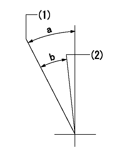
(1)Set the pump speed at aa
(2)Set the pump speed at bb.
----------
aa=1150r/min bb=690r/min
----------
a=21deg+-5deg b=7deg+-5deg
----------
aa=1150r/min bb=690r/min
----------
a=21deg+-5deg b=7deg+-5deg
0000000901
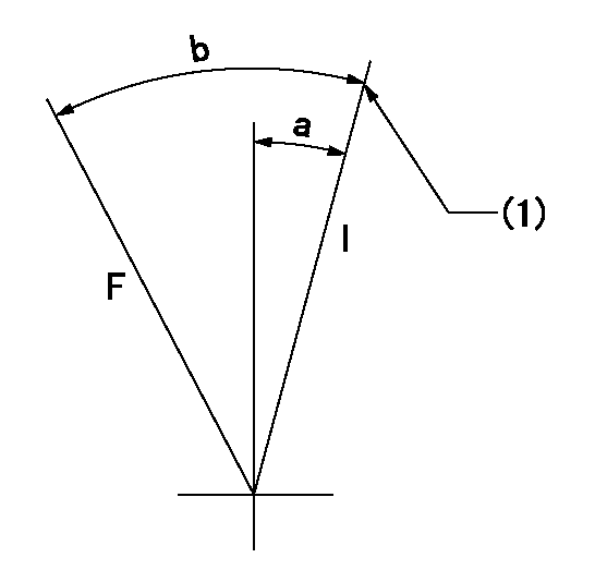
F:Full load
I:Idle
(1)Stopper bolt setting
----------
----------
a=10deg+-5deg b=28deg+-3deg
----------
----------
a=10deg+-5deg b=28deg+-3deg
Stop lever angle
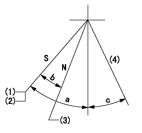
N:Pump normal
S:Stop the pump.
(1)Rack position = aa
(2)Stopper bolt setting
(3)Rack position bb
(4)Free (at shipping)
----------
aa=4-0.5mm bb=11.7mm
----------
a=43deg+7deg-5deg b=21.5deg+-5deg c=(10.5deg)
----------
aa=4-0.5mm bb=11.7mm
----------
a=43deg+7deg-5deg b=21.5deg+-5deg c=(10.5deg)
0000001501 MICRO SWITCH
Adjustment of the micro-switch
Adjust the bolt to obtain the following lever position when the micro-switch is ON.
(1)Speed N1
(2)Rack position Ra
----------
N1=325+-5r/min Ra=5.6mm
----------
----------
N1=325+-5r/min Ra=5.6mm
----------
Timing setting

(1)Pump vertical direction
(2)Coupling's key groove position at No 1 cylinder's beginning of injection
(3)-
(4)-
----------
----------
a=(40deg)
----------
----------
a=(40deg)
Information:
Start By:a. remove crankshaft vibration damper and pulley
Keep all parts clean from contaminants. Contaminants put into the system may cause rapid wear and shortened component life.
When replacement of the front seal is made, a replacement of the wear sleeve must also be made.
1. Remove the two bolts, washers, clamp (1), retainer (2) and the O-ring seal.2. Use tool (A) and a press to remove seal (3).3. Install the O-ring seal, retainer (2) and the two bolts, washers, and clamp (1). 4. Install tool (C) in the bore of retainer (2) as shown.5. Install tool (B) between tool (C) and the wear sleeve. Turn tool (B) with a wrench until the edge of the tool makes a flat place (crease) in the wear sleeve. Do this in two or more places until the wear sleeve is loose.6. Remove tool (C) and the wear sleeve by hand.Install Crankshaft Front Seal And Wear Sleeve
1. Install crankshaft front seal (1) and wear sleeve (2) with tool (A) as follows:a. Put clean engine oil on the seal lip of seal (1) and on the outside diameter of wear sleeve (2). Install seal (1) on wear sleeve (2) as shown.b. Use 6V1541 Quick Cure Primer to clean the outside diameter of crankshaft (3) and the inside diameter of wear sleeve (2).c. Put 9S3265 Retaining Compound on the outside diameter of crankshaft (3) and the inside diameter of wear sleeve (2). Make sure the lip of the seal is toward the engine and the outside diameter bevel of the wear sleeve is toward the outside of the engine.d. Put wear sleeve (2) with seal (1) on the front of the crankshaft as shown in illustration B20159P1. Install tool (A). Tighten the bolt in tool (A) until the inside surface of the installer in tooling (A) makes contact with the end of the crankshaft.End By:a. install crankshaft vibration damper and pulley
Have questions with 106873-2221?
Group cross 106873-2221 ZEXEL
Mitsubishi
Mitsubishi
Mitsubishi
106873-2221
9 400 618 345
ME091689
INJECTION-PUMP ASSEMBLY
8DC11
8DC11