Information injection-pump assembly
BOSCH
9 400 618 334
9400618334
ZEXEL
106873-2103
1068732103
MITSUBISHI
ME091556
me091556
Rating:
Service parts 106873-2103 INJECTION-PUMP ASSEMBLY:
1.
_
7.
COUPLING PLATE
8.
_
9.
_
11.
Nozzle and Holder
ME091275
12.
Open Pre:MPa(Kqf/cm2)
17.7{180}/21.6{220}
15.
NOZZLE SET
Include in #1:
106873-2103
as INJECTION-PUMP ASSEMBLY
Cross reference number
BOSCH
9 400 618 334
9400618334
ZEXEL
106873-2103
1068732103
MITSUBISHI
ME091556
me091556
Zexel num
Bosch num
Firm num
Name
106873-2103
9 400 618 334
ME091556 MITSUBISHI
INJECTION-PUMP ASSEMBLY
8DC10 K 14CD INJECTION PUMP ASSY PE8P PE
8DC10 K 14CD INJECTION PUMP ASSY PE8P PE
Calibration Data:
Adjustment conditions
Test oil
1404 Test oil ISO4113 or {SAEJ967d}
1404 Test oil ISO4113 or {SAEJ967d}
Test oil temperature
degC
40
40
45
Nozzle and nozzle holder
105780-8140
Bosch type code
EF8511/9A
Nozzle
105780-0000
Bosch type code
DN12SD12T
Nozzle holder
105780-2080
Bosch type code
EF8511/9
Opening pressure
MPa
17.2
Opening pressure
kgf/cm2
175
Injection pipe
Outer diameter - inner diameter - length (mm) mm 8-3-600
Outer diameter - inner diameter - length (mm) mm 8-3-600
Overflow valve opening pressure
kPa
157
123
191
Overflow valve opening pressure
kgf/cm2
1.6
1.25
1.95
Tester oil delivery pressure
kPa
157
157
157
Tester oil delivery pressure
kgf/cm2
1.6
1.6
1.6
Direction of rotation (viewed from drive side)
Right R
Right R
Injection timing adjustment
Direction of rotation (viewed from drive side)
Right R
Right R
Injection order
1-2-7-3-
4-5-6-8
Pre-stroke
mm
4.8
4.75
4.85
Beginning of injection position
Governor side NO.1
Governor side NO.1
Difference between angles 1
Cyl.1-2 deg. 45 44.5 45.5
Cyl.1-2 deg. 45 44.5 45.5
Difference between angles 2
Cal 1-7 deg. 90 89.5 90.5
Cal 1-7 deg. 90 89.5 90.5
Difference between angles 3
Cal 1-3 deg. 135 134.5 135.5
Cal 1-3 deg. 135 134.5 135.5
Difference between angles 4
Cal 1-4 deg. 180 179.5 180.5
Cal 1-4 deg. 180 179.5 180.5
Difference between angles 5
Cal 1-5 deg. 225 224.5 225.5
Cal 1-5 deg. 225 224.5 225.5
Difference between angles 6
Cal 1-6 deg. 270 269.5 270.5
Cal 1-6 deg. 270 269.5 270.5
Difference between angles 7
Cal 1-8 deg. 315 314.5 315.5
Cal 1-8 deg. 315 314.5 315.5
Injection quantity adjustment
Adjusting point
-
Rack position
10.4
Pump speed
r/min
650
650
650
Each cylinder's injection qty
mm3/st.
127.5
123.7
131.3
Basic
*
Fixing the rack
*
Standard for adjustment of the maximum variation between cylinders
*
Injection quantity adjustment_02
Adjusting point
C
Rack position
6.2+-0.5
Pump speed
r/min
225
225
225
Each cylinder's injection qty
mm3/st.
15.5
13.2
17.8
Fixing the rack
*
Standard for adjustment of the maximum variation between cylinders
*
Injection quantity adjustment_03
Adjusting point
A
Rack position
R1(10.4)
Pump speed
r/min
650
650
650
Average injection quantity
mm3/st.
127.5
126.5
128.5
Basic
*
Fixing the lever
*
Injection quantity adjustment_04
Adjusting point
B
Rack position
R1(10.4)
Pump speed
r/min
1100
1100
1100
Average injection quantity
mm3/st.
130.8
128.8
132.8
Fixing the lever
*
Injection quantity adjustment_05
Adjusting point
E
Rack position
-
Pump speed
r/min
100
100
100
Average injection quantity
mm3/st.
140
120
160
Fixing the lever
*
Remarks
After startup boost setting
After startup boost setting
Timer adjustment
Pump speed
r/min
900--
Advance angle
deg.
0
0
0
Remarks
Start
Start
Timer adjustment_02
Pump speed
r/min
850
Advance angle
deg.
0.5
Timer adjustment_03
Pump speed
r/min
1100
Advance angle
deg.
4.5
4
5
Remarks
Finish
Finish
Test data Ex:
Governor adjustment
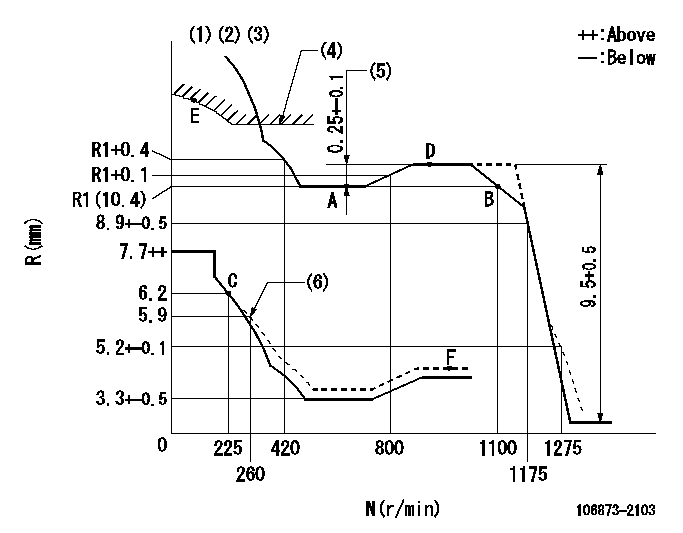
N:Pump speed
R:Rack position (mm)
(1)Lever ratio: RT
(2)Target shim dimension: TH
(3)Tolerance for racks not indicated: +-0.05mm.
(4)Excess fuel setting for starting: SXL
(5)Rack difference between N = N1 and N = N2
(6)Damper spring setting
----------
RT=1 TH=2.8mm SXL=11.7+-0.1mm N1=900r/min N2=650r/min
----------
----------
RT=1 TH=2.8mm SXL=11.7+-0.1mm N1=900r/min N2=650r/min
----------
Speed control lever angle

F:Full speed
----------
----------
a=19deg+-5deg
----------
----------
a=19deg+-5deg
0000000901

F:Full load
I:Idle
(1)Stopper bolt setting
----------
----------
a=10deg+-5deg b=26.5deg+-3deg
----------
----------
a=10deg+-5deg b=26.5deg+-3deg
Stop lever angle

S:Stop the pump.
(1)Rack position = aa
(2)Stopper bolt setting
(3)Free (at shipping)
----------
aa=4.1-0.5mm
----------
a=10.5deg+-5deg b=55.5deg+7deg-5deg
----------
aa=4.1-0.5mm
----------
a=10.5deg+-5deg b=55.5deg+7deg-5deg
0000001501 MICRO SWITCH
Adjustment of the micro-switch
Adjust the bolt to obtain the following lever position when the micro-switch is ON.
(1)Speed N1
(2)Rack position Ra
----------
N1=325r/min Ra=5.7+-0.1mm
----------
----------
N1=325r/min Ra=5.7+-0.1mm
----------
Timing setting

(1)Pump vertical direction
(2)Coupling's key groove position at No 1 cylinder's beginning of injection
(3)B.T.D.C.: aa
(4)-
----------
aa=12deg
----------
a=(40deg)
----------
aa=12deg
----------
a=(40deg)
Information:
Engine Crankshaft Will Not Turn
Possible Causes/Corrections Low Or No Battery VoltageCheck battery voltage. If battery voltage is less than 8 volts for a 12 volt system, or 16 volts for a 24 volt system, put a charge to the battery. If battery will not hold a charge, load test the battery as shown in the Electrical System of the Testing and Adjusting Section of this Service Manual. Defective Switch, Defective Wiring Or Connection In Switch CircuitWith ignition switch in START position, check voltage at switch connection on starter solenoid. If there is no voltage, or if the voltage is low at this connection, check wiring, connections, ignition switch, and magnetic switch (if used). Defective Cable Or Connection; Battery To StarterWith ignition switch in the START position, check voltage at connection of battery cable to starter. If there is no voltage, or if the voltage is low at this connection and there is good voltage at the battery, check for defective cable or connection between the
Possible Causes/Corrections Low Or No Battery VoltageCheck battery voltage. If battery voltage is less than 8 volts for a 12 volt system, or 16 volts for a 24 volt system, put a charge to the battery. If battery will not hold a charge, load test the battery as shown in the Electrical System of the Testing and Adjusting Section of this Service Manual. Defective Switch, Defective Wiring Or Connection In Switch CircuitWith ignition switch in START position, check voltage at switch connection on starter solenoid. If there is no voltage, or if the voltage is low at this connection, check wiring, connections, ignition switch, and magnetic switch (if used). Defective Cable Or Connection; Battery To StarterWith ignition switch in the START position, check voltage at connection of battery cable to starter. If there is no voltage, or if the voltage is low at this connection and there is good voltage at the battery, check for defective cable or connection between the
Have questions with 106873-2103?
Group cross 106873-2103 ZEXEL
Mitsubishi
106873-2103
9 400 618 334
ME091556
INJECTION-PUMP ASSEMBLY
8DC10
8DC10