Information injection-pump assembly
ZEXEL
106872-4100
1068724100
NIIGATA-URAWA
W2C47130A
w2c47130a
Rating:
Service parts 106872-4100 INJECTION-PUMP ASSEMBLY:
1.
_
5.
AUTOM. ADVANCE MECHANIS
7.
COUPLING PLATE
8.
_
9.
_
11.
Nozzle and Holder
12.
Open Pre:MPa(Kqf/cm2)
22.5(260)
15.
NOZZLE SET
Include in #1:
106872-4100
as INJECTION-PUMP ASSEMBLY
Cross reference number
ZEXEL
106872-4100
1068724100
NIIGATA-URAWA
W2C47130A
w2c47130a
Zexel num
Bosch num
Firm num
Name
Calibration Data:
Adjustment conditions
Test oil
1404 Test oil ISO4113 or {SAEJ967d}
1404 Test oil ISO4113 or {SAEJ967d}
Test oil temperature
degC
40
40
45
Nozzle and nozzle holder
105780-8140
Bosch type code
EF8511/9A
Nozzle
105780-0000
Bosch type code
DN12SD12T
Nozzle holder
105780-2080
Bosch type code
EF8511/9
Opening pressure
MPa
17.2
Opening pressure
kgf/cm2
175
Injection pipe
Outer diameter - inner diameter - length (mm) mm 8-3-600
Outer diameter - inner diameter - length (mm) mm 8-3-600
Overflow valve
134424-1420
Overflow valve opening pressure
kPa
162
147
177
Overflow valve opening pressure
kgf/cm2
1.65
1.5
1.8
Tester oil delivery pressure
kPa
157
157
157
Tester oil delivery pressure
kgf/cm2
1.6
1.6
1.6
Direction of rotation (viewed from drive side)
Right R
Right R
Injection timing adjustment
Direction of rotation (viewed from drive side)
Right R
Right R
Injection order
1-8-7-5-
4-3-6-2
Pre-stroke
mm
3.9
3.85
3.95
Beginning of injection position
Governor side NO.1
Governor side NO.1
Difference between angles 1
Cal 1-8 deg. 45 44.5 45.5
Cal 1-8 deg. 45 44.5 45.5
Difference between angles 2
Cal 1-7 deg. 90 89.5 90.5
Cal 1-7 deg. 90 89.5 90.5
Difference between angles 3
Cal 1-5 deg. 135 134.5 135.5
Cal 1-5 deg. 135 134.5 135.5
Difference between angles 4
Cal 1-4 deg. 180 179.5 180.5
Cal 1-4 deg. 180 179.5 180.5
Difference between angles 5
Cal 1-3 deg. 225 224.5 225.5
Cal 1-3 deg. 225 224.5 225.5
Difference between angles 6
Cal 1-6 deg. 270 269.5 270.5
Cal 1-6 deg. 270 269.5 270.5
Difference between angles 7
Cyl.1-2 deg. 315 314.5 315.5
Cyl.1-2 deg. 315 314.5 315.5
Injection quantity adjustment
Adjusting point
A
Rack position
14.4
Pump speed
r/min
750
750
750
Average injection quantity
mm3/st.
226.7
221.7
231.7
Max. variation between cylinders
%
0
-3
3
Basic
*
Fixing the rack
*
Injection quantity adjustment_02
Adjusting point
B
Rack position
13.6
Pump speed
r/min
900
900
900
Average injection quantity
mm3/st.
210.9
205.9
215.9
Max. variation between cylinders
%
0
-4
4
Fixing the rack
*
Injection quantity adjustment_03
Adjusting point
C
Rack position
7.1+-0.5
Pump speed
r/min
250
250
250
Average injection quantity
mm3/st.
30
27
33
Max. variation between cylinders
%
0
-10
10
Fixing the rack
*
Remarks
Adjust only variation between cylinders; adjust governor according to governor specifications.
Adjust only variation between cylinders; adjust governor according to governor specifications.
Test data Ex:
Governor adjustment
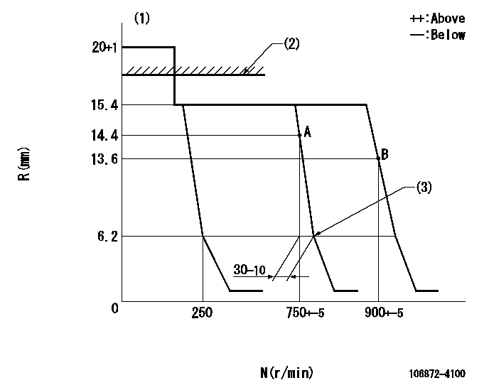
N:Pump speed
R:Rack position (mm)
(1)Target notch: K
(2)RACK LIMIT: RAL
(3)Idle sub spring setting: L1.
----------
K=5 RAL=16.4+0.2mm L1=6.2-0.5mm
----------
----------
K=5 RAL=16.4+0.2mm L1=6.2-0.5mm
----------
Speed control lever angle
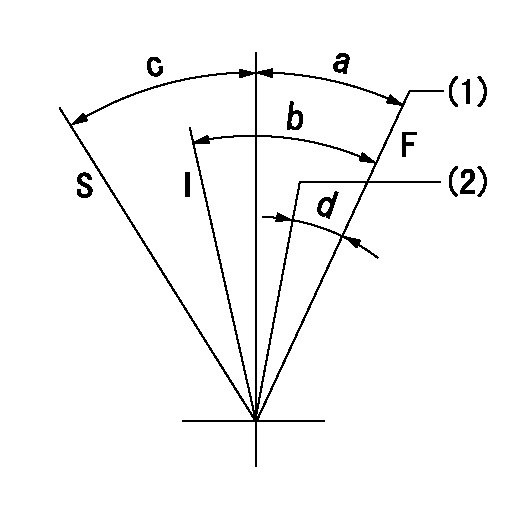
F:Full speed
I:Idle
S:Stop
(1)Speed set at aa (setting at shipping)
(2)Set the pump speed at bb.
----------
aa=900r/min bb=750r/min
----------
a=(10deg)+-5deg b=(32deg)+-5deg c=32deg+-3deg d=(8deg)+-5deg
----------
aa=900r/min bb=750r/min
----------
a=(10deg)+-5deg b=(32deg)+-5deg c=32deg+-3deg d=(8deg)+-5deg
Stop lever angle
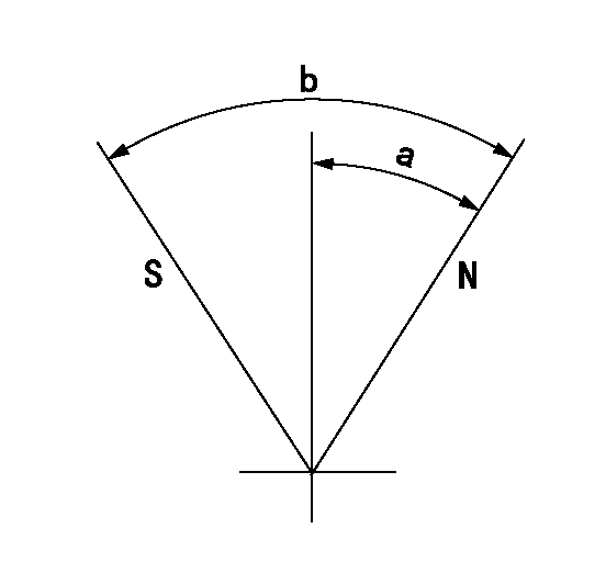
N:Pump normal
S:Stop the pump.
----------
----------
a=42deg+-5deg b=82deg+-5deg
----------
----------
a=42deg+-5deg b=82deg+-5deg
Timing setting

(1)Pump vertical direction
(2)Position of coupling's key groove at the No 2 cylinder's beginning of injection
(3)-
(4)-
----------
----------
a=(20deg)
----------
----------
a=(20deg)
Information:
1. Disconnect oil supply line (1) and oil drain tube (2). Remove the four mounting nuts and remove the turbocharger. Remove the gasket. The following steps are for the installation of the turbocharger.2. Apply 5P3931 Anti-Seize to turbocharger mounting studs. Position turbocharger gasket and turbocharger, then Install the four mounting nuts. Tighten the four mounting nuts to a torque of 54 5 N m (40 4 lb.ft.).3. Position gaskets and install drain tube (2) and supply line (1).Disassemble And Assemble Turbocharger
Start By:a. remove turbocharger 1. Remove bolts (1) and (2). Remove the compressor and turbine housings.2. Remove nut (3) and compressor wheel (4). Slide out turbine wheel (5) and shaft.3. Remove adapter plate snap ring (6).4. Use two screwdrivers and remove adapter plate (7).5. Remove bushings (8), spacers (9), and seals (10).6. Remove snap ring (11) and bushing (12).7. Remove snap ring (13) and bushing (14). The following steps are for the assembly of the turbocharger.8. Install bushing (12) and snap ring (11). Repeat for bushing (14) and snap ring (13).9. With th seals and shield (15) in place, install shaft and turbine wheel assembly (5).10. Install the spacers, bushings, plate, seals and adapter plate. Install the snap ring (not illustrated).
Do not allow any of the 7M7456 Locktite to get on the shaft. Damage to the turbocharger may occur.
11. Install compressor wheel (4) on the shaft. Put one drop of 7M7456 Locktite on the threads and install nut (3). Tighten nut (3) to a torque of 15.6 .7 N m (138 6 lb.in.).12. Position the turbine and compressor housings. Put 5P3931 Anti-Seize Compound on the bolts and install. Tighten bolts (1) for the compressor cover to a torque of 7.3 .6 N m (65 5 lb.in.). Tighten bolts (2), for the turbine housing to a torque of 15.8 .6 N m (140 5 lb.in.).End by:a. Install turbocharger