Information injection-pump assembly
ZEXEL
106871-9024
1068719024

Rating:
Service parts 106871-9024 INJECTION-PUMP ASSEMBLY:
1.
_
7.
COUPLING PLATE
8.
_
9.
_
11.
Nozzle and Holder
12.
Open Pre:MPa(Kqf/cm2)
17.7{180}/21.6{220}
15.
NOZZLE SET
Include in #1:
106871-9024
as INJECTION-PUMP ASSEMBLY
Cross reference number
ZEXEL
106871-9024
1068719024
Zexel num
Bosch num
Firm num
Name
106871-9024
INJECTION-PUMP ASSEMBLY
Calibration Data:
Adjustment conditions
Test oil
1404 Test oil ISO4113 or {SAEJ967d}
1404 Test oil ISO4113 or {SAEJ967d}
Test oil temperature
degC
40
40
45
Nozzle and nozzle holder
105780-8140
Bosch type code
EF8511/9A
Nozzle
105780-0000
Bosch type code
DN12SD12T
Nozzle holder
105780-2080
Bosch type code
EF8511/9
Opening pressure
MPa
17.2
Opening pressure
kgf/cm2
175
Injection pipe
Outer diameter - inner diameter - length (mm) mm 8-3-600
Outer diameter - inner diameter - length (mm) mm 8-3-600
Overflow valve
134424-1320
Overflow valve opening pressure
kPa
157
123
191
Overflow valve opening pressure
kgf/cm2
1.6
1.25
1.95
Tester oil delivery pressure
kPa
157
157
157
Tester oil delivery pressure
kgf/cm2
1.6
1.6
1.6
Direction of rotation (viewed from drive side)
Right R
Right R
Injection timing adjustment
Direction of rotation (viewed from drive side)
Right R
Right R
Injection order
1-2-7-3-
4-5-6-8
Pre-stroke
mm
4.8
4.75
4.85
Beginning of injection position
Governor side NO.1
Governor side NO.1
Difference between angles 1
Cyl.1-2 deg. 45 44.5 45.5
Cyl.1-2 deg. 45 44.5 45.5
Difference between angles 2
Cal 1-7 deg. 90 89.5 90.5
Cal 1-7 deg. 90 89.5 90.5
Difference between angles 3
Cal 1-3 deg. 135 134.5 135.5
Cal 1-3 deg. 135 134.5 135.5
Difference between angles 4
Cal 1-4 deg. 180 179.5 180.5
Cal 1-4 deg. 180 179.5 180.5
Difference between angles 5
Cal 1-5 deg. 225 224.5 225.5
Cal 1-5 deg. 225 224.5 225.5
Difference between angles 6
Cal 1-6 deg. 270 269.5 270.5
Cal 1-6 deg. 270 269.5 270.5
Difference between angles 7
Cal 1-8 deg. 315 314.5 315.5
Cal 1-8 deg. 315 314.5 315.5
Injection quantity adjustment
Adjusting point
-
Rack position
9.5
Pump speed
r/min
700
700
700
Each cylinder's injection qty
mm3/st.
118
114.5
121.5
Basic
*
Fixing the rack
*
Standard for adjustment of the maximum variation between cylinders
*
Injection quantity adjustment_02
Adjusting point
F
Rack position
5.8+-0.5
Pump speed
r/min
450
450
450
Each cylinder's injection qty
mm3/st.
17
15.3
18.7
Fixing the rack
*
Standard for adjustment of the maximum variation between cylinders
*
Injection quantity adjustment_03
Adjusting point
A
Rack position
R1(9.5)
Pump speed
r/min
700
700
700
Average injection quantity
mm3/st.
118
117
119
Basic
*
Fixing the lever
*
Injection quantity adjustment_04
Adjusting point
B
Rack position
R1(9.5)
Pump speed
r/min
1100
1100
1100
Average injection quantity
mm3/st.
124
118.8
129.2
Difference in delivery
mm3/st.
10.4
10.4
10.4
Fixing the lever
*
Injection quantity adjustment_05
Adjusting point
C
Rack position
6.1+-0.5
Pump speed
r/min
225
225
225
Each cylinder's injection qty
mm3/st.
20
17
23
Fixing the rack
*
Remarks
(check)
(check)
Injection quantity adjustment_06
Adjusting point
E
Rack position
-
Pump speed
r/min
100
100
100
Average injection quantity
mm3/st.
95
55
135
Fixing the lever
*
Remarks
After startup boost setting
After startup boost setting
Timer adjustment
Pump speed
r/min
950--
Advance angle
deg.
0
0
0
Remarks
Start
Start
Timer adjustment_02
Pump speed
r/min
900
Advance angle
deg.
0.5
Timer adjustment_03
Pump speed
r/min
1000
Advance angle
deg.
1.7
1.2
2.2
Timer adjustment_04
Pump speed
r/min
1150
Advance angle
deg.
6.5
6
7
Remarks
Finish
Finish
Test data Ex:
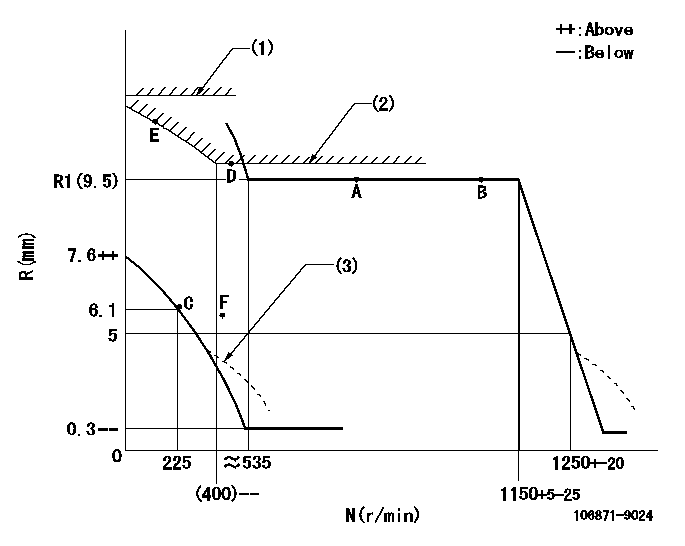
Governor adjustment

N:Pump speed
R:Rack position (mm)
(1)Rack limit using the stop lever: R1
(2)Excess fuel setting for starting: SXL
(3)Damper spring setting: DL
----------
R1=11.6+-0.1mm SXL=(R1+0.2)+-0.1mm DL=4.3-0.2mm
----------
----------
R1=11.6+-0.1mm SXL=(R1+0.2)+-0.1mm DL=4.3-0.2mm
----------
0000000901

F:Full load
I:Idle
(1)Stopper bolt setting
----------
----------
a=16deg+-5deg b=18deg+-3deg
----------
----------
a=16deg+-5deg b=18deg+-3deg
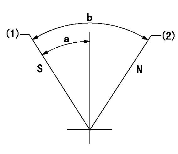
Stop lever angle

N:Pump normal
S:Stop the pump.
(1)Rack position = aa, stopper bolt setting
(2)Rack position bb
----------
aa=4-0.5mm bb=11.6+-0.1mm
----------
a=5deg+-6deg b=34deg+-6deg
----------
aa=4-0.5mm bb=11.6+-0.1mm
----------
a=5deg+-6deg b=34deg+-6deg
0000001501 MICRO SWITCH
Switch adjustment
Adjust the bolt so that the lower lever position is obtained when the switch is turned ON.
(1)Speed N1
(2)Rack position Ra
----------
N1=325+-25r/min Ra=5.6mm
----------
----------
N1=325+-25r/min Ra=5.6mm
----------
Timing setting

(1)Pump vertical direction
(2)Coupling's key groove position at No 1 cylinder's beginning of injection
(3)-
(4)-
----------
----------
a=(40deg)
----------
----------
a=(40deg)
Information:
Bearings
Anti-Friction Bearings
When an anti-friction bearing is removed, cover it to keep out dirt and abrasives. Wash the bearings in nonflammable cleaning solution and allow them to drain dry. The bearings may be dried with compressed air, but DO NOT SPIN THE BEARING. Discard the bearings if the races and balls or rollers are pitted, scored or burned. If the bearing is serviceable, coat it with oil and wrap it in clean paper. DO NOT unwrap new bearings until time of installation.The life of an anti-friction bearing will be shortened if not properly lubricated.Double Row, Tapered Roller
Double row, tapered roller bearings are precision fit during manufacture and the components are not interchangeable. The cups, cones and spacers are usually etched with the same serial number and letter designator. If no letter designators are found, wire the components together to assure correct installation. Reusable bearing components should be installed in their original positions.Heating Bearings
Bearings which require expansion for installation should be heated in oil not to exceed 121°C (250°F). When more than one part is heated to aid in assembly, they must be allowed to cool and then pressed together again. Parts often separate as they cool and shrink.Installation
Lubricate new or used bearings before installation. Bearings that are to be preloaded must have a film of oil over the entire assembly to obtain accurate preloading. When installing a bearing, spacer or washer against a shoulder on a shaft, be sure the chamfered side is toward the shoulder. When pressing bearings into a retainer or bore, apply pressure to the outer race. If the bearing is pressed on the shaft, apply pressure on the inner race.Preload
Preload is an initial force placed on the bearing at the time of assembly.Determine preload or end clearance form the Specifications Section of this Service Manual. Care should be exercised in applying preload. Misapplication of preload to bearings requiring end clearance can result in bearing failure.Sleeve Bearings
DO NOT INSTALL SLEEVE BEARINGS WITH A HAMMER. Use a press, if possible and apply the pressure directly in line with the bore. If it is necessary to drive on a bearing, use a driver or a bar with a smooth flat end. If a sleeve bearing has an oil hole, align it with the oil hole in the mating part.
Have questions with 106871-9024?
Group cross 106871-9024 ZEXEL
Dpico
Hyundai
106871-9024
INJECTION-PUMP ASSEMBLY
