Information injection-pump assembly
ZEXEL
106871-9020
1068719020

Rating:
Cross reference number
ZEXEL
106871-9020
1068719020
Zexel num
Bosch num
Firm num
Name
Calibration Data:
Adjustment conditions
Test oil
1404 Test oil ISO4113 or {SAEJ967d}
1404 Test oil ISO4113 or {SAEJ967d}
Test oil temperature
degC
40
40
45
Nozzle and nozzle holder
105780-8140
Bosch type code
EF8511/9A
Nozzle
105780-0000
Bosch type code
DN12SD12T
Nozzle holder
105780-2080
Bosch type code
EF8511/9
Opening pressure
MPa
17.2
Opening pressure
kgf/cm2
175
Injection pipe
Outer diameter - inner diameter - length (mm) mm 8-3-600
Outer diameter - inner diameter - length (mm) mm 8-3-600
Overflow valve opening pressure
kPa
157
123
191
Overflow valve opening pressure
kgf/cm2
1.6
1.25
1.95
Tester oil delivery pressure
kPa
157
157
157
Tester oil delivery pressure
kgf/cm2
1.6
1.6
1.6
Direction of rotation (viewed from drive side)
Right R
Right R
Injection timing adjustment
Direction of rotation (viewed from drive side)
Right R
Right R
Injection order
1-2-7-3-
4-5-6-8
Pre-stroke
mm
4.8
4.75
4.85
Beginning of injection position
Governor side NO.1
Governor side NO.1
Difference between angles 1
Cyl.1-2 deg. 45 44.5 45.5
Cyl.1-2 deg. 45 44.5 45.5
Difference between angles 2
Cal 1-7 deg. 90 89.5 90.5
Cal 1-7 deg. 90 89.5 90.5
Difference between angles 3
Cal 1-3 deg. 135 134.5 135.5
Cal 1-3 deg. 135 134.5 135.5
Difference between angles 4
Cal 1-4 deg. 180 179.5 180.5
Cal 1-4 deg. 180 179.5 180.5
Difference between angles 5
Cal 1-5 deg. 225 224.5 225.5
Cal 1-5 deg. 225 224.5 225.5
Difference between angles 6
Cal 1-6 deg. 270 269.5 270.5
Cal 1-6 deg. 270 269.5 270.5
Difference between angles 7
Cal 1-8 deg. 315 314.5 315.5
Cal 1-8 deg. 315 314.5 315.5
Injection quantity adjustment
Adjusting point
-
Rack position
9.5
Pump speed
r/min
700
700
700
Each cylinder's injection qty
mm3/st.
118
114.5
121.5
Basic
*
Fixing the rack
*
Standard for adjustment of the maximum variation between cylinders
*
Injection quantity adjustment_02
Adjusting point
F
Rack position
5.8+-0.5
Pump speed
r/min
450
450
450
Each cylinder's injection qty
mm3/st.
17
15.3
18.7
Fixing the rack
*
Standard for adjustment of the maximum variation between cylinders
*
Injection quantity adjustment_03
Adjusting point
A
Rack position
R1(9.5)
Pump speed
r/min
700
700
700
Average injection quantity
mm3/st.
118
117
119
Basic
*
Fixing the lever
*
Injection quantity adjustment_04
Adjusting point
B
Rack position
R1(9.5)
Pump speed
r/min
1100
1100
1100
Average injection quantity
mm3/st.
124
118.8
129.2
Difference in delivery
mm3/st.
10.4
10.4
10.4
Fixing the lever
*
Injection quantity adjustment_05
Adjusting point
C
Rack position
6.1+-0.5
Pump speed
r/min
225
225
225
Each cylinder's injection qty
mm3/st.
20
17
23
Fixing the rack
*
Remarks
(check)
(check)
Injection quantity adjustment_06
Adjusting point
E
Rack position
11.6+-0.
5
Pump speed
r/min
100
100
100
Average injection quantity
mm3/st.
125
105
145
Fixing the lever
*
Remarks
Rack limit using stop lever.
Rack limit using stop lever.
Timer adjustment
Pump speed
r/min
950--
Advance angle
deg.
0
0
0
Remarks
Beginning of advance.
Beginning of advance.
Timer adjustment_02
Pump speed
r/min
900
Advance angle
deg.
0.5
Timer adjustment_03
Pump speed
r/min
1000
Advance angle
deg.
1.7
1.2
2.2
Timer adjustment_04
Pump speed
r/min
1150
Advance angle
deg.
6.5
6
7
Remarks
Finish
Finish
Test data Ex:
Governor adjustment

N:Pump speed
R:Rack position (mm)
(1)Rack limit using stop lever
(2)Excess fuel setting for starting: SXL
(3)Damper spring setting: DL
----------
SXL=R1+0.2mm DL=4.3-0.2mm
----------
----------
SXL=R1+0.2mm DL=4.3-0.2mm
----------
0000000901

F:Full load
I:Idle
(1)Stopper bolt setting
----------
----------
a=16deg+-5deg b=18deg+-3deg
----------
----------
a=16deg+-5deg b=18deg+-3deg
Stop lever angle
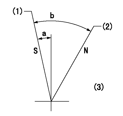
N:Pump normal
S:Stop the pump.
(1)Rack position = aa, stopper bolt setting
(2)Point E setting
(3)Using reverse lever (top)
----------
aa=4-0.5mm
----------
a=5deg+-6deg b=(34deg)+-6deg
----------
aa=4-0.5mm
----------
a=5deg+-6deg b=(34deg)+-6deg
0000001501 MICRO SWITCH
Adjustment of the micro-switch
Adjust the bolt to obtain the following lever position when the micro-switch is ON.
(1)Speed N1
(2)Rack position Ra
----------
N1=325+-5r/min Ra=5.6mm
----------
----------
N1=325+-5r/min Ra=5.6mm
----------
Timing setting

(1)Pump vertical direction
(2)Coupling's key groove position at No 1 cylinder's beginning of injection
(3)-
(4)-
----------
----------
a=(40deg)
----------
----------
a=(40deg)
Information:
Loose Belt(s)
Loose fan or water pump belts will cause a reduction in air or water flow. Tighten the belts according to V-Belt Tension Chart that is shown in Specification section of this Service Manual.Bad Hose(s)
Bad hoses with leaks can normally be seen. Hoses that have no visual leaks can "collapse" (pull together) during operation and cause a restriction in the flow of coolant. Hoses become soft and/or get cracks after a period of time. Hoses must be changed after 50,000 miles or a year of use. The inside can become loose, and the loose particles of the hose can cause a restriction in the flow of coolant.Shunt Line Restriction
A restriction of the shunt line from the radiator top tank to the engine front cover, or a shunt line not installed correctly, will cause a reduction in water pump efficiency. The result will be low coolant flow and overheating.Shutters Not Opening Correctly
Check the opening temperature of the shutters. The shutters must be completely closed at a temperature below the fully open temperature of the water temperature regulators. Also, verify that fan control switches or viscous fans are operating correctly.Bad Water Temperature Regulators
A regulator that does not open, or only opens part of the way, can cause above normal heating. To test the thermostats, see the Testing and Adjusting section of this Service Manual.Bad Water Pump
A water pump with a loose impeller does not pump enough coolant for correct engine cooling. A loose impeller can be found by removing the water pump, and by pushing the shaft back and pulling it forward. If the impeller has no damage, check the impeller clearance. The clearance between the impeller and the housing is 0.56 to 1.50 mm (.022 to .059 in).Air in Cooling System
Air can get into the cooling system in different ways. The most common causes are not filling the cooling system correctly, and combustion gas leaking into the system. Combustion gas can get into the system through inside cracks or bad cylinder head gaskets. Air in the cooling system causes a reduction in coolant flow and bubbles in the coolant. Air bubbles hold coolant away from engine parts, preventing heat flow.Air in the cooling system can be found by the Bottle Test. The equipment needed to make this test is a one pint bottle, a bucket of water, and a hose which will fit the end of the overflow pipe of the radiator.Before testing, make sure the cooling system is filled correctly. Use a wire to hold the relief valve in the radiator cap open. Install the radiator cap and tighten it. Put the hose over the end of the overflow pipe.Start the engine and operate it at high idle rpm for a minimum of five minutes after the engine is at normal operating temperature. Use a cover on the radiator core to keep the engine at operating temperature. After five or more minutes at operating temperature, place the loose end of the hose in the bottle filled with water.