Information injection-pump assembly
ZEXEL
106871-8840
1068718840
HINO
220007450A
220007450a

Rating:
Cross reference number
ZEXEL
106871-8840
1068718840
HINO
220007450A
220007450a
Zexel num
Bosch num
Firm num
Name
Calibration Data:
Adjustment conditions
Test oil
1404 Test oil ISO4113 or {SAEJ967d}
1404 Test oil ISO4113 or {SAEJ967d}
Test oil temperature
degC
40
40
45
Nozzle and nozzle holder
105780-8140
Bosch type code
EF8511/9A
Nozzle
105780-0000
Bosch type code
DN12SD12T
Nozzle holder
105780-2080
Bosch type code
EF8511/9
Opening pressure
MPa
17.2
Opening pressure
kgf/cm2
175
Injection pipe
Outer diameter - inner diameter - length (mm) mm 8-3-600
Outer diameter - inner diameter - length (mm) mm 8-3-600
Overflow valve
134424-1020
Overflow valve opening pressure
kPa
127
107
147
Overflow valve opening pressure
kgf/cm2
1.3
1.1
1.5
Tester oil delivery pressure
kPa
157
157
157
Tester oil delivery pressure
kgf/cm2
1.6
1.6
1.6
Direction of rotation (viewed from drive side)
Right R
Right R
Injection timing adjustment
Direction of rotation (viewed from drive side)
Right R
Right R
Injection order
1-8-6-2-
7-5-4-3
Pre-stroke
mm
4.5
4.44
4.5
Beginning of injection position
Drive side NO.1
Drive side NO.1
Difference between angles 1
Cal 1-8 deg. 45 44.75 45.25
Cal 1-8 deg. 45 44.75 45.25
Difference between angles 2
Cal 1-6 deg. 90 89.75 90.25
Cal 1-6 deg. 90 89.75 90.25
Difference between angles 3
Cyl.1-2 deg. 135 134.75 135.25
Cyl.1-2 deg. 135 134.75 135.25
Difference between angles 4
Cal 1-7 deg. 180 179.75 180.25
Cal 1-7 deg. 180 179.75 180.25
Difference between angles 5
Cal 1-5 deg. 225 224.75 225.25
Cal 1-5 deg. 225 224.75 225.25
Difference between angles 6
Cal 1-4 deg. 270 269.75 270.25
Cal 1-4 deg. 270 269.75 270.25
Difference between angles 7
Cal 1-3 deg. 315 314.75 315.25
Cal 1-3 deg. 315 314.75 315.25
Injection quantity adjustment
Adjusting point
A
Rack position
9
Pump speed
r/min
700
700
700
Average injection quantity
mm3/st.
153
151
155
Max. variation between cylinders
%
0
-2
2
Basic
*
Fixing the lever
*
Injection quantity adjustment_02
Adjusting point
B
Rack position
8.8
Pump speed
r/min
500
500
500
Average injection quantity
mm3/st.
150
147
153
Fixing the lever
*
Injection quantity adjustment_03
Adjusting point
D
Rack position
9.2
Pump speed
r/min
1100
1100
1100
Average injection quantity
mm3/st.
150.4
142.4
158.4
Fixing the lever
*
Injection quantity adjustment_04
Adjusting point
E
Rack position
7.95
Pump speed
r/min
1200
1200
1200
Average injection quantity
mm3/st.
122
116
128
Fixing the lever
*
Injection quantity adjustment_05
Adjusting point
F
Rack position
3.8+-0.5
Pump speed
r/min
225
225
225
Average injection quantity
mm3/st.
12.1
9.1
15.1
Max. variation between cylinders
%
0
-15
15
Fixing the rack
*
Injection quantity adjustment_06
Adjusting point
H
Rack position
-
Pump speed
r/min
100
100
100
Fixing the lever
*
Remarks
After startup boost setting
After startup boost setting
Timer adjustment
Pump speed
r/min
660
Advance angle
deg.
0.3
Load
1/4
Timer adjustment_02
Pump speed
r/min
800--
Advance angle
deg.
1
0.7
1.3
Load
4/4
Timer adjustment_03
Pump speed
r/min
880+50
Advance angle
deg.
1
0.7
1.3
Load
3/4
Timer adjustment_04
Pump speed
r/min
1100-50
Advance angle
deg.
4.75
4.45
5.05
Load
4/4
Remarks
Finish
Finish
Test data Ex:
Governor adjustment
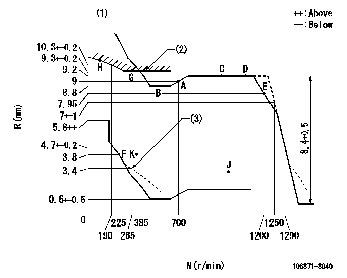
N:Pump speed
R:Rack position (mm)
(1)Tolerance for racks not indicated: +-0.05mm.
(2)Excess fuel setting for starting: SXL (N = N1)
(3)Damper spring setting
----------
SXL=9.75+-0.1mm N1=300r/min
----------
----------
SXL=9.75+-0.1mm N1=300r/min
----------
Speed control lever angle

F:Full speed
----------
----------
a=15deg+-5deg
----------
----------
a=15deg+-5deg
0000000901
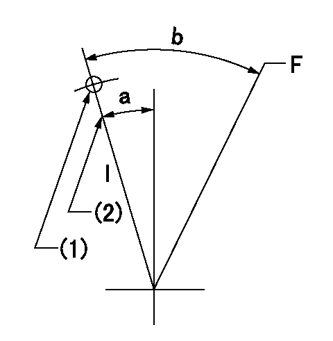
F:Full load
I:Idle
(1)Use the hole at R = aa
(2)Stopper bolt setting
----------
aa=65mm
----------
a=10deg+-5deg b=43.5deg+-3deg
----------
aa=65mm
----------
a=10deg+-5deg b=43.5deg+-3deg
Stop lever angle

N:Engine manufacturer's normal use
S:Stop the pump.
(1)Rack position = aa
(2)Rack position bb
(3)Set the stopper bolt (apply red paint).
(4)Free (at delivery)
----------
aa=11.8mm bb=2-0.5mm
----------
a=(13deg) b=46.5deg+-5deg c=29deg+-5deg
----------
aa=11.8mm bb=2-0.5mm
----------
a=(13deg) b=46.5deg+-5deg c=29deg+-5deg
0000001501 RACK SENSOR

(VR) measurement voltage
(I) Part number of the control unit
(G) Apply red paint.
(H): End surface of the pump
1. Rack sensor adjustment (-0620)
(1)Fix the speed control lever at the full position
(2)Set the speed to N1 r/min.
(If the boost compensator is provided, apply boost pressure.)
(3)Adjust the bobbin (A) so that the rack sensor's output voltage is VR+-0.01.
(4)At that time, rack position must be Ra.
(5)Apply G at two places.
Connecting part between the joint (B) and the nut (F)
Connecting part between the joint (B) and the end surface of the pump (H)
----------
N1=900r/min Ra=9.2mm
----------
----------
N1=900r/min Ra=9.2mm
----------
Timing setting

(1)Pump vertical direction
(2)Coupling's key groove position at No 1 cylinder's beginning of injection
(3)-
(4)-
----------
----------
a=(80deg)
----------
----------
a=(80deg)
Information:
start by:a) remove oil pan1. Turn the crankshaft until two pistons are at bottom center. Remove connecting rod caps (1) from the two connecting rods. Remove the lower half of the bearings from the caps.2. Push the connecting rods away from the crankshaft and remove the upper half of the bearings.
Be careful not to damage the crankshaft journals. Do not turn the crankshaft while any of the connecting rod caps are removed.
Install the bearings dry when the clearance checks are made. Put clean engine oil on the bearings for final assembly.3. Clean the surfaces where the bearings fit. Install the upper half of the bearing in the connecting rod. Pull the connecting rod slowly on to the crankshaft.4. Install lower half of the bearing in the cap.
When the connecting rod caps are installed, make sure that the numbers on the side of the caps are next to and respective with the number on the side of the connecting rods.
Typical Example5. Check the bearing clearance with Plastigage (A). Put Plastigage (A) on the bearing.6. Put 2P2506 Thread Lubricant on the threads of the rod bolts and seat surfaces of the nuts.
Do not use an impact wrench to tighten the nuts the additional 60 5°.
Do not turn the crankshaft when Plastigage (A) is in position. 7. Put caps (1) in position on the connecting rods and install the nuts. Tighten the nuts to a torque of 40 4 N m (30 3 lb.ft.). Put a mark on each nut and the end of each bolt. Tighten the nuts 60 5° more.8. Remove the cap. Measure the thickness of Plastigage (A). The rod bearing clearance must be 0.053 to 0.140 mm (.0021 to .0055 in.). The maximum permissible clearance is 0.15 mm (.006 in.).9. Put the caps in position on the connecting rods and install the nuts. Tighten the nuts to a torque of 40 4 N m (30 3 lb.ft.). Put a mark on each nut and the end of each bolt. Tighten the nuts 60 5° more.10. Do Steps 1 through 9 again for other bearings. end by:a) install oil pan