Information injection-pump assembly
BOSCH
9 400 618 305
9400618305
ZEXEL
106871-8820
1068718820
HINO
220801540A
220801540a
Rating:
Service parts 106871-8820 INJECTION-PUMP ASSEMBLY:
1.
_
7.
COUPLING PLATE
8.
_
9.
_
11.
Nozzle and Holder
23600-1530
12.
Open Pre:MPa(Kqf/cm2)
18.1{185}
15.
NOZZLE SET
Include in #1:
106871-8820
as INJECTION-PUMP ASSEMBLY
Cross reference number
BOSCH
9 400 618 305
9400618305
ZEXEL
106871-8820
1068718820
HINO
220801540A
220801540a
Zexel num
Bosch num
Firm num
Name
106871-8820
9 400 618 305
220801540A HINO
INJECTION-PUMP ASSEMBLY
EF750 * K 14CD INJECTION PUMP ASSY PE8P PE
EF750 * K 14CD INJECTION PUMP ASSY PE8P PE
Calibration Data:
Adjustment conditions
Test oil
1404 Test oil ISO4113 or {SAEJ967d}
1404 Test oil ISO4113 or {SAEJ967d}
Test oil temperature
degC
40
40
45
Nozzle and nozzle holder
105780-8140
Bosch type code
EF8511/9A
Nozzle
105780-0000
Bosch type code
DN12SD12T
Nozzle holder
105780-2080
Bosch type code
EF8511/9
Opening pressure
MPa
17.2
Opening pressure
kgf/cm2
175
Injection pipe
Outer diameter - inner diameter - length (mm) mm 8-3-600
Outer diameter - inner diameter - length (mm) mm 8-3-600
Overflow valve
134424-1020
Overflow valve opening pressure
kPa
127
107
147
Overflow valve opening pressure
kgf/cm2
1.3
1.1
1.5
Tester oil delivery pressure
kPa
157
157
157
Tester oil delivery pressure
kgf/cm2
1.6
1.6
1.6
Direction of rotation (viewed from drive side)
Right R
Right R
Injection timing adjustment
Direction of rotation (viewed from drive side)
Right R
Right R
Injection order
1-8-6-2-
7-5-4-3
Pre-stroke
mm
4.4
4.34
4.4
Beginning of injection position
Drive side NO.1
Drive side NO.1
Difference between angles 1
Cal 1-8 deg. 45 44.75 45.25
Cal 1-8 deg. 45 44.75 45.25
Difference between angles 2
Cal 1-6 deg. 90 89.75 90.25
Cal 1-6 deg. 90 89.75 90.25
Difference between angles 3
Cyl.1-2 deg. 135 134.75 135.25
Cyl.1-2 deg. 135 134.75 135.25
Difference between angles 4
Cal 1-7 deg. 180 179.75 180.25
Cal 1-7 deg. 180 179.75 180.25
Difference between angles 5
Cal 1-5 deg. 225 224.75 225.25
Cal 1-5 deg. 225 224.75 225.25
Difference between angles 6
Cal 1-4 deg. 270 269.75 270.25
Cal 1-4 deg. 270 269.75 270.25
Difference between angles 7
Cal 1-3 deg. 315 314.75 315.25
Cal 1-3 deg. 315 314.75 315.25
Injection quantity adjustment
Adjusting point
A
Rack position
9.5
Pump speed
r/min
500
500
500
Average injection quantity
mm3/st.
120
117
123
Max. variation between cylinders
%
0
-4
4
Fixing the lever
*
Injection quantity adjustment_02
Adjusting point
B
Rack position
9.6
Pump speed
r/min
700
700
700
Average injection quantity
mm3/st.
121.8
119.8
123.8
Max. variation between cylinders
%
0
-2
2
Basic
*
Fixing the lever
*
Injection quantity adjustment_03
Adjusting point
C
Rack position
10.4
Pump speed
r/min
1100
1100
1100
Average injection quantity
mm3/st.
145
142
148
Max. variation between cylinders
%
0
-4
4
Fixing the lever
*
Injection quantity adjustment_04
Adjusting point
D
Rack position
5.4
Pump speed
r/min
225
225
225
Average injection quantity
mm3/st.
11.5
8.5
14.5
Max. variation between cylinders
%
0
-15
15
Fixing the rack
*
Injection quantity adjustment_05
Adjusting point
E
Rack position
-
Pump speed
r/min
100
100
100
Average injection quantity
mm3/st.
140
140
160
Fixing the lever
*
Remarks
After startup boost setting
After startup boost setting
Injection quantity adjustment_06
Adjusting point
H
Rack position
7.6+-0.5
Pump speed
r/min
1175
1175
1175
Average injection quantity
mm3/st.
126
121
131
Max. variation between cylinders
%
0
-4
4
Fixing the lever
*
Timer adjustment
Pump speed
r/min
850
Advance angle
deg.
0.5
Timer adjustment_02
Pump speed
r/min
1000
Advance angle
deg.
1.7
1.2
2.2
Timer adjustment_03
Pump speed
r/min
1100
Advance angle
deg.
3.5
3.2
3.8
Remarks
Finish
Finish
Test data Ex:
Governor adjustment
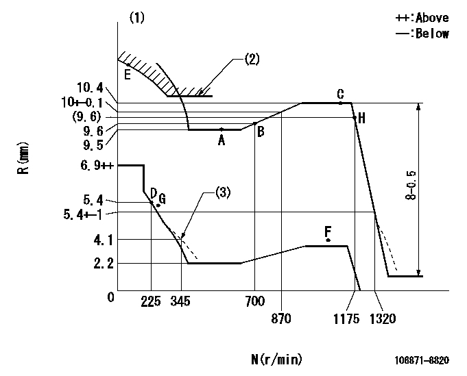
N:Pump speed
R:Rack position (mm)
(1)Tolerance for racks not indicated: +-0.05mm.
(2)Excess fuel setting for starting: SXL (N = N1)
(3)Damper spring setting
----------
SXL=10.4+0.2mm N1=350r/min
----------
----------
SXL=10.4+0.2mm N1=350r/min
----------
Speed control lever angle
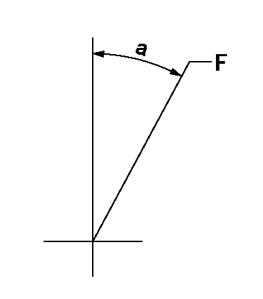
F:Full speed
----------
----------
a=21.5deg+-5deg
----------
----------
a=21.5deg+-5deg
0000000901

F:Full load
I:Idle
(1)Stopper bolt setting
(2)Use the hole at R = aa
----------
aa=50mm
----------
a=39deg+-3deg b=39deg+-5deg
----------
aa=50mm
----------
a=39deg+-3deg b=39deg+-5deg
Stop lever angle
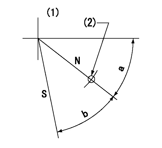
N:Pump normal
S:Stop the pump.
(1)After assembling lever on end of solenoid
(2)Use the hole at R = aa
----------
aa=30mm
----------
a=39deg+-5deg b=40deg+-5deg
----------
aa=30mm
----------
a=39deg+-5deg b=40deg+-5deg
Timing setting

(1)Pump vertical direction
(2)Coupling's key groove position at No 1 cylinder's beginning of injection
(3)-
(4)-
----------
----------
a=(80deg)
----------
----------
a=(80deg)
Information:
start by:a) remove exhaust manifoldb) remove air inlet manifoldc) remove valve coversd) remove fuel injection linese) remove fuel injection nozzles1. Remove the coolant from the cooling system. 2. Remove clamp (2) from water sleeves (1) in each cylinder head. Push the water sleeves into the timing gear cover with tool (A) and a screwdriver. 3. Remove bolt (3) from the bracket on the dipstick tube. 4. Remove bolts (4) and stud (5) from the heads.
Make sure the fuel injection nozzles are removed before the cylinder heads are removed. The fuel injection nozzles go through the cylinder heads and the nozzle tips can be broken off if the nozzles are not removed from the heads.
5. Install tooling (B) and fasten a hoist. Remove bolts (7), cylinder head (6) and the gasket. The weight of the cylinder head is 54 kg (120 lb.).Install Cylinder Heads
1. Clean the contact surfaces of the cylinder head and cylinder block. Make sure the surfaces are clean and dry. Install a new cylinder head gasket. Clean the bore in the cylinder head for the water sleeves. Put oil on the seals on the water sleeves.2. Install tooling (B) in the cylinder head. Fasten a hoist and put the cylinder head in position on the cylinder block.3. Put 6V4876 Molykote Lubricant on the bolt threads and install the bolts that hold the cylinder head in their correct location. Tighten the bolts in the cylinder head according to the HEAD BOLT TORQUE CHART.
The higher cylinder head bolt torque may be used on earlier engines ONLY if the bolts are replaced with the later higher strength bolts (seven dash marks on the bolt head). If the earlier bolts are tightened to the later torque specification, they may yield (stretch) and lose their clamping force.
4. Install water sleeve into cylinder head with tool (A). Install the clamp on the water sleeves.5. Fill the cooling system with coolant to the correct level. end by:a) install fuel injection nozzlesb) install rocker shafts and push rodsc) install valve coversd) install air inlet manifolde) install exhaust manifold
Illustration 1. Bolt head identification.Disassemble Cylinder Heads
start by: a) remove cylinder heads1. Fasten a hoist and put the cylinder head in position on tool (A). Use adapter plates (1) from tooling (A) to hold the head in place. 2. Put the valve springs under compression with tool (C). 3. Remove the locks from the valves. Earlier engines have an inner valve spring. Later engines have only one valve spring and a spacer instead of inner spring.4. Remove tool (C), retainer, spring, washer and valve from the cylinder head. Put identification on the valve as to its location in the cylinder head. 5. Check the valve spring force with tool (B). For the correct spring force, see the subject VALVES in SPECIFICATIONS.6. Do Steps 2 through 5 for the remainder of the valves.7. Remove the valve seat inserts with tooling (D). The valve guides are part of the cylinder head. Measure the bore in each valve guide 19.0
Have questions with 106871-8820?
Group cross 106871-8820 ZEXEL
Hino
106871-8820
9 400 618 305
220801540A
INJECTION-PUMP ASSEMBLY
EF750
EF750
