Information injection-pump assembly
BOSCH
9 400 618 304
9400618304
ZEXEL
106871-8810
1068718810
HINO
220007360A
220007360a

Rating:
Cross reference number
BOSCH
9 400 618 304
9400618304
ZEXEL
106871-8810
1068718810
HINO
220007360A
220007360a
Zexel num
Bosch num
Firm num
Name
Calibration Data:
Adjustment conditions
Test oil
1404 Test oil ISO4113 or {SAEJ967d}
1404 Test oil ISO4113 or {SAEJ967d}
Test oil temperature
degC
40
40
45
Nozzle and nozzle holder
105780-8140
Bosch type code
EF8511/9A
Nozzle
105780-0000
Bosch type code
DN12SD12T
Nozzle holder
105780-2080
Bosch type code
EF8511/9
Opening pressure
MPa
17.2
Opening pressure
kgf/cm2
175
Injection pipe
Outer diameter - inner diameter - length (mm) mm 8-3-600
Outer diameter - inner diameter - length (mm) mm 8-3-600
Overflow valve
134424-0820
Overflow valve opening pressure
kPa
127
107
147
Overflow valve opening pressure
kgf/cm2
1.3
1.1
1.5
Tester oil delivery pressure
kPa
157
157
157
Tester oil delivery pressure
kgf/cm2
1.6
1.6
1.6
Direction of rotation (viewed from drive side)
Right R
Right R
Injection timing adjustment
Direction of rotation (viewed from drive side)
Right R
Right R
Injection order
1-8-6-2-
7-5-4-3
Pre-stroke
mm
4.8
4.74
4.8
Beginning of injection position
Drive side NO.1
Drive side NO.1
Difference between angles 1
Cal 1-8 deg. 45 44.75 45.25
Cal 1-8 deg. 45 44.75 45.25
Difference between angles 2
Cal 1-6 deg. 90 89.75 90.25
Cal 1-6 deg. 90 89.75 90.25
Difference between angles 3
Cyl.1-2 deg. 135 134.75 135.25
Cyl.1-2 deg. 135 134.75 135.25
Difference between angles 4
Cal 1-7 deg. 180 179.75 180.25
Cal 1-7 deg. 180 179.75 180.25
Difference between angles 5
Cal 1-5 deg. 225 224.75 225.25
Cal 1-5 deg. 225 224.75 225.25
Difference between angles 6
Cal 1-4 deg. 270 269.75 270.25
Cal 1-4 deg. 270 269.75 270.25
Difference between angles 7
Cal 1-3 deg. 315 314.75 315.25
Cal 1-3 deg. 315 314.75 315.25
Injection quantity adjustment
Adjusting point
A
Rack position
9
Pump speed
r/min
700
700
700
Average injection quantity
mm3/st.
139
137
141
Max. variation between cylinders
%
0
-2
2
Basic
*
Fixing the lever
*
Injection quantity adjustment_02
Adjusting point
B
Rack position
9.2
Pump speed
r/min
1100
1100
1100
Average injection quantity
mm3/st.
140
137
143
Fixing the lever
*
Injection quantity adjustment_03
Adjusting point
F
Rack position
3.9+-0.5
Pump speed
r/min
225
225
225
Average injection quantity
mm3/st.
9.7
6.7
12.7
Max. variation between cylinders
%
0
-15
15
Fixing the rack
*
Injection quantity adjustment_04
Adjusting point
G
Rack position
-
Pump speed
r/min
100
100
100
Average injection quantity
mm3/st.
140
140
Fixing the lever
*
Remarks
After startup boost setting
After startup boost setting
Timer adjustment
Pump speed
r/min
710--
Advance angle
deg.
0
0
0
Load
1/4
Remarks
Start
Start
Timer adjustment_02
Pump speed
r/min
660
Advance angle
deg.
0.3
Load
1/4
Timer adjustment_03
Pump speed
r/min
800
Advance angle
deg.
0.7
0.4
1
Load
4/4
Timer adjustment_04
Pump speed
r/min
880
Advance angle
deg.
0.7
0.4
1
Load
3/4
Timer adjustment_05
Pump speed
r/min
1100
Advance angle
deg.
5.25
4.95
5.55
Load
4/4
Remarks
Finish
Finish
Test data Ex:
Governor adjustment
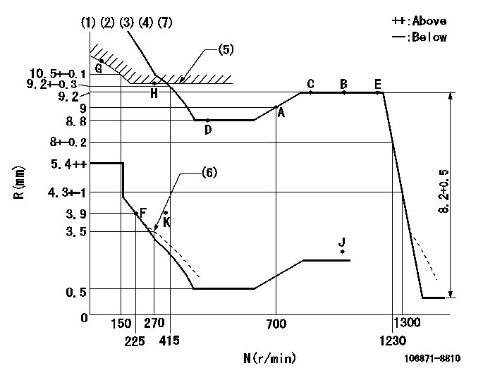
N:Pump speed
R:Rack position (mm)
(1)Lever ratio: RT
(2)Target shim dimension: TH
(3)Tolerance for racks not indicated: +-0.05mm.
(4)Supplied with torque spring not set.
(5)Excess fuel setting for starting: SXL (N = N1)
(6)Damper spring setting
(7)Set idle at point K (N = N2, R = R2) and confirm that the injection quantity does not exceed Q1 at point J (N = N3).
----------
RT=0.8 TH=2.9mm SXL=10+-0.1mm N1=300r/min N2=325r/min R2=3.9mm N3=1100r/min Q1=2mm3/st
----------
----------
RT=0.8 TH=2.9mm SXL=10+-0.1mm N1=300r/min N2=325r/min R2=3.9mm N3=1100r/min Q1=2mm3/st
----------
Speed control lever angle

F:Full speed
----------
----------
a=(16deg)+-5deg
----------
----------
a=(16deg)+-5deg
0000000901
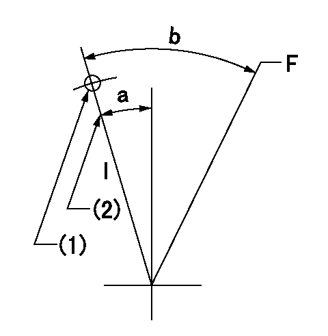
F:Full load
I:Idle
(1)Use the hole at R = aa
(2)Stopper bolt setting
----------
aa=65mm
----------
a=10deg+-5deg b=44deg+-3deg
----------
aa=65mm
----------
a=10deg+-5deg b=44deg+-3deg
Stop lever angle

N:Pump normal
S:Stop the pump.
----------
----------
a=10deg+-5deg b=64deg+-5deg
----------
----------
a=10deg+-5deg b=64deg+-5deg
0000001501 RACK SENSOR

(VR) measurement voltage
(I) Part number of the control unit
(G) Apply red paint.
(H): End surface of the pump
1. Rack sensor adjustment (-0620)
(1)Fix the speed control lever at the full position
(2)Set the speed to N1 r/min.
(If the boost compensator is provided, apply boost pressure.)
(3)Adjust the bobbin (A) so that the rack sensor's output voltage is VR+-0.01.
(4)At that time, rack position must be Ra.
(5)Apply G at two places.
Connecting part between the joint (B) and the nut (F)
Connecting part between the joint (B) and the end surface of the pump (H)
----------
N1=1100r/min Ra=9.2mm
----------
----------
N1=1100r/min Ra=9.2mm
----------
Timing setting

(1)Pump vertical direction
(2)Coupling's key groove position at No 1 cylinder's beginning of injection
(3)-
(4)-
----------
----------
a=(80deg)
----------
----------
a=(80deg)
Information:
1. Remove carbon seal dam (2) with pliers. Remove compression seal (1). 2. Install a new compression seal on the nozzle. Install a new carbon seal dam with tool (B).3. Make sure the bore in the cylinder head and the fuel inlet fittings are clean.4. Install new O-ring seals on adapter (3) and fuel injection nozzle (4).5. Install the fuel injection nozzle in the head. Turn and push the nozzle into its correct position. Never put lubricant on the nozzle or bore in the cylinder head. 6. Install the adapter in the head. Connect the nozzle and fuel injection line to the adapter. Tighten the nuts to a torque of 40 7 N m (30 5 lb.ft.).7. Install the spacer and clamp (5) that hold the nozzle to the cylinder head. end by:a) install rocker shaftsDisassemble Fuel Injection Nozzles (9N3979 & 1W5829)
start by:a) remove fuel injection nozzles Do not disassemble any nozzle until test has shown it is needed. Check each nozzle with tool (A) for leakage, the pressure, at which the nozzle opens, and the shape and amount of fuel (spray pattern) that comes out of the nozzle. Do not clean or make an adjustment to any nozzle that has a large (excessive) amount of return leakage. Excessive return leakage can be an indication of nozzle failures that cannot be corrected with an adjustment or cleaning and can cause engine damage. See TESTING 9N3979 & 1W5829 FUEL INJECTION NOZZLES in TESTING AND ADJUSTING.
Keep the work area and all tools extra clean. Be careful not to cause damage to the parts while the nozzles are disassembled and assembled.
1. Remove cap (1) from the fuel injection nozzle.2. Put the nozzle in tool (B). Put tool (B) and the nozzle in a vise. Do not put any part of a nozzle directly in a vise. Loosen locknut (2) while the lift adjustment screw is held. Turn the lift adjustment screw (3) counterclockwise one turn. Hold the lift adjustment screw (3) with a 5/64" hex wrench and remove the locknut (2).
If the lift adjustment screw is not turned counterclockwise one turn, the valve can be bent or the seat for the valve can be damaged when the pressure adjustment screw is turned.
3. Loosen the locknut (4) that holds the pressure adjustment screw. Use tool (D) to hold the pressure adjustment screw. 4. While the nozzle is held in one hand, tilt the nozzle and remove the pressure adjusting screw and locknut, spring, seat and valve. 5. If the valve does not slide out of the nozzle, install tool (C) and remove valve as follows: a) Push valve into nozzle with tool (C) until valve is against bottom of nozzle.b) Push down on body of tool (C) to engage collet on valve with tool (C). c) Turn nut counterclockwise and remove valve from the nozzle body. Put the parts in solvent to loosen carbon and deposits of foreign material. The body is assembled with an epoxy material and must