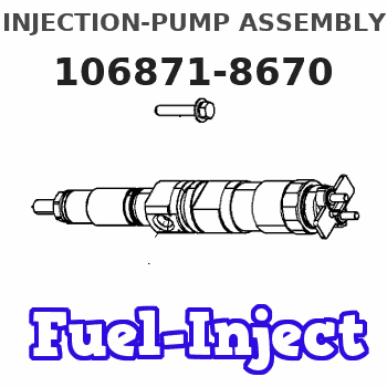
Information injection-pump assembly
ZEXEL
106871-8670
1068718670
HINO
220400084A
220400084a
Rating:
Cross reference number
ZEXEL
106871-8670
1068718670
HINO
220400084A
220400084a
Zexel num
Bosch num
Firm num
Name
106871-8670
220400084A HINO
INJECTION-PUMP ASSEMBLY
F17E * K
F17E * K
Calibration Data:
Adjustment conditions
Test oil
1404 Test oil ISO4113 or {SAEJ967d}
1404 Test oil ISO4113 or {SAEJ967d}
Test oil temperature
degC
40
40
45
Nozzle and nozzle holder
105780-8140
Bosch type code
EF8511/9A
Nozzle
105780-0000
Bosch type code
DN12SD12T
Nozzle holder
105780-2080
Bosch type code
EF8511/9
Opening pressure
MPa
17.2
Opening pressure
kgf/cm2
175
Injection pipe
Outer diameter - inner diameter - length (mm) mm 8-3-600
Outer diameter - inner diameter - length (mm) mm 8-3-600
Overflow valve
134424-0820
Overflow valve opening pressure
kPa
127
107
147
Overflow valve opening pressure
kgf/cm2
1.3
1.1
1.5
Tester oil delivery pressure
kPa
157
157
157
Tester oil delivery pressure
kgf/cm2
1.6
1.6
1.6
Direction of rotation (viewed from drive side)
Right R
Right R
Injection timing adjustment
Direction of rotation (viewed from drive side)
Right R
Right R
Injection order
1-8-6-2-
7-5-4-3
Pre-stroke
mm
4.8
4.74
4.8
Beginning of injection position
Drive side NO.1
Drive side NO.1
Difference between angles 1
Cal 1-8 deg. 45 44.75 45.25
Cal 1-8 deg. 45 44.75 45.25
Difference between angles 2
Cal 1-6 deg. 90 89.75 90.25
Cal 1-6 deg. 90 89.75 90.25
Difference between angles 3
Cyl.1-2 deg. 135 134.75 135.25
Cyl.1-2 deg. 135 134.75 135.25
Difference between angles 4
Cal 1-7 deg. 180 179.75 180.25
Cal 1-7 deg. 180 179.75 180.25
Difference between angles 5
Cal 1-5 deg. 225 224.75 225.25
Cal 1-5 deg. 225 224.75 225.25
Difference between angles 6
Cal 1-4 deg. 270 269.75 270.25
Cal 1-4 deg. 270 269.75 270.25
Difference between angles 7
Cal 1-3 deg. 315 314.75 315.25
Cal 1-3 deg. 315 314.75 315.25
Injection quantity adjustment
Adjusting point
A
Rack position
9
Pump speed
r/min
700
700
700
Average injection quantity
mm3/st.
139
137
141
Max. variation between cylinders
%
0
-2
2
Basic
*
Fixing the lever
*
Injection quantity adjustment_02
Adjusting point
B
Rack position
9.2
Pump speed
r/min
1100
1100
1100
Average injection quantity
mm3/st.
140
137
143
Fixing the lever
*
Injection quantity adjustment_03
Adjusting point
F
Rack position
3.9+-0.5
Pump speed
r/min
225
225
225
Average injection quantity
mm3/st.
9.7
6.7
12.7
Max. variation between cylinders
%
0
-15
15
Fixing the rack
*
Injection quantity adjustment_04
Adjusting point
G
Rack position
-
Pump speed
r/min
100
100
100
Average injection quantity
mm3/st.
140
140
Fixing the lever
*
Remarks
After startup boost setting
After startup boost setting
Timer adjustment
Pump speed
r/min
710--
Advance angle
deg.
0
0
0
Load
1/4
Remarks
Start
Start
Timer adjustment_02
Pump speed
r/min
660
Advance angle
deg.
0.3
Load
1/4
Timer adjustment_03
Pump speed
r/min
800
Advance angle
deg.
0.7
0.4
1
Load
4/4
Timer adjustment_04
Pump speed
r/min
880
Advance angle
deg.
0.7
0.4
1
Load
3/4
Timer adjustment_05
Pump speed
r/min
1100
Advance angle
deg.
5.25
4.95
5.55
Load
4/4
Remarks
Finish
Finish
Test data Ex:
Governor adjustment
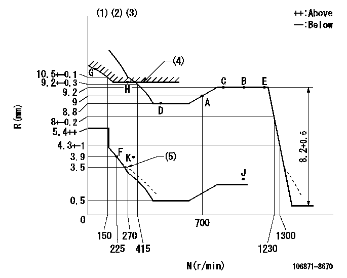
N:Pump speed
R:Rack position (mm)
(1)Tolerance for racks not indicated: +-0.05mm.
(2)Supplied with torque spring not set.
(3)Set idle at point K (N = N1, R = R1) and confirm that the injection quantity at N = N2 at point J is Q1.
(4)Excess fuel setting for starting: SXL (N = N3)
(5)Damper spring setting
----------
N1=325r/min R1=3.9mm N2=1100r/min Q1=2mm3/st SXL=10+-0.1mm N3=300r/min
----------
----------
N1=325r/min R1=3.9mm N2=1100r/min Q1=2mm3/st SXL=10+-0.1mm N3=300r/min
----------
Speed control lever angle

F:Full speed
----------
----------
a=(16deg)+-5deg
----------
----------
a=(16deg)+-5deg
0000000901
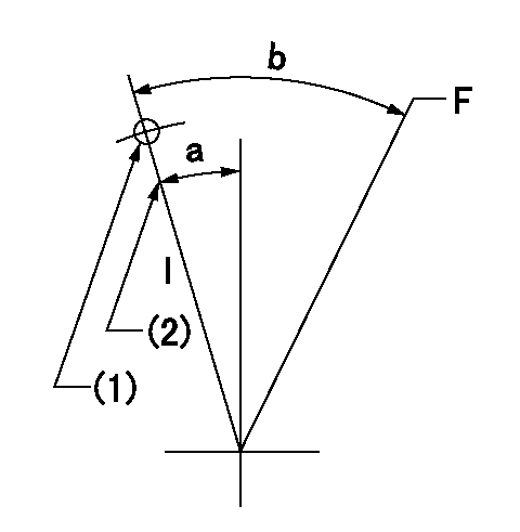
F:Full load
I:Idle
(1)Use the hole at R = aa
(2)Stopper bolt setting
----------
aa=65mm
----------
a=10deg+-5deg b=44deg+-3deg
----------
aa=65mm
----------
a=10deg+-5deg b=44deg+-3deg
Stop lever angle
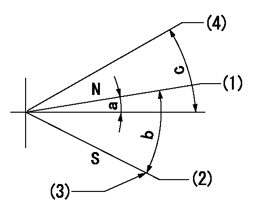
N:Engine manufacturer's normal use
S:Stop the pump.
(1)Rack position = aa
(2)Rack position bb
(3)Set the stopper bolt (apply red paint).
(4)Free (at delivery)
----------
aa=12mm bb=2.5-0.5mm
----------
a=1deg+-5deg b=27.5deg+-5deg c=(34deg)
----------
aa=12mm bb=2.5-0.5mm
----------
a=1deg+-5deg b=27.5deg+-5deg c=(34deg)
0000001501 RACK SENSOR

(VR) measurement voltage
(I) Part number of the control unit
(G) Apply red paint.
(H): End surface of the pump
1. Rack sensor adjustment (-0620)
(1)Fix the speed control lever at the full position
(2)Set the speed to N1 r/min.
(If the boost compensator is provided, apply boost pressure.)
(3)Adjust the bobbin (A) so that the rack sensor's output voltage is VR+-0.01.
(4)At that time, rack position must be Ra.
(5)Apply G at two places.
Connecting part between the joint (B) and the nut (F)
Connecting part between the joint (B) and the end surface of the pump (H)
----------
N1=1100r/min Ra=9.2mm
----------
----------
N1=1100r/min Ra=9.2mm
----------
Timing setting

(1)Pump vertical direction
(2)Coupling's key groove position at No 1 cylinder's beginning of injection
(3)-
(4)-
----------
----------
a=(80deg)
----------
----------
a=(80deg)
Information:
This troubleshooting guide, when followed exactly as shown, can be an aid for the serviceman to find the cause of existing problems. The information from the measurements will also show proof if there is any basis for the complaint.Be sure to get a good description of the problem from the operator and/or the person who owns the vehicle. What they tell you about the problem can save you time and make the repair job faster and easier.Low Power And High Fuel Consumption Problems
The troubleshooting charts that follow provide a definite sequence to be followed for a logical, one by one elimination of many variables. The encircled numbers do not designate steps, but are references to detailed instructions that can not be shown on the chart. Always read the written material that corresponds with the encircled numbers on the charts.The Primary Engine Tests consist of quick and easy procedures that could identify the problem with a minimum loss of time. Always make these tests before starting the more involved troubleshooting charts.The necessary instruments to check each problem in sequence are shown on the chart. If the correct instrument is not available for the test, do not continue. The vehicle must be sent to a shop where the necessary tools are available.Whenever a problem is found and corrected, always run the test again to that point to be sure there is not a combination of problems. When the problem has been corrected and the complaint resolved, stop the test. Do not continue through the complete procedure just because it is there.When investigating possible causes, follow the letter sequence shown. Possible causes are arranged in order from more probable/easiest to check to less probable/more complex to check.Other Problems: Vehicle Or Vehicle Operation, Misfiring And Running Rough, Too Much Exhaust Smoke, Difficult Starting, Cooling System, Loss Of Coolant, Or Fuel In Crankcase Oil.
The probable causes of a problem are given in the order they most commonly take place. Check the probable causes in the same order that they are given. When troubleshooting, use the section on recommended procedures which follow each chart to check and make the necessary corrections for each probable cause.Engine Vibration Problem
The troubleshooting chart provides a definite sequence to be followed for a logical procedure to determine the frequency and amplitude of vibration so that the source of the vibration can be located and corrected.
Have questions with 106871-8670?
Group cross 106871-8670 ZEXEL
Hino
Hino
Hino
Hino
106871-8670
220400084A
INJECTION-PUMP ASSEMBLY
F17E
F17E