Information injection-pump assembly
BOSCH
9 400 618 287
9400618287
ZEXEL
106871-8620
1068718620
HINO
220006930A
220006930a

Rating:
Service parts 106871-8620 INJECTION-PUMP ASSEMBLY:
1.
_
7.
COUPLING PLATE
8.
_
9.
_
11.
Nozzle and Holder
23600-2240B
12.
Open Pre:MPa(Kqf/cm2)
14.7{150}/21.6{220}
14.
NOZZLE
Include in #1:
106871-8620
as INJECTION-PUMP ASSEMBLY
Cross reference number
BOSCH
9 400 618 287
9400618287
ZEXEL
106871-8620
1068718620
HINO
220006930A
220006930a
Zexel num
Bosch num
Firm num
Name
106871-8620
9 400 618 287
220006930A HINO
INJECTION-PUMP ASSEMBLY
F17E K 14CD INJECTION PUMP ASSY PE8P PE
F17E K 14CD INJECTION PUMP ASSY PE8P PE
Calibration Data:
Adjustment conditions
Test oil
1404 Test oil ISO4113 or {SAEJ967d}
1404 Test oil ISO4113 or {SAEJ967d}
Test oil temperature
degC
40
40
45
Nozzle and nozzle holder
105780-8140
Bosch type code
EF8511/9A
Nozzle
105780-0000
Bosch type code
DN12SD12T
Nozzle holder
105780-2080
Bosch type code
EF8511/9
Opening pressure
MPa
17.2
Opening pressure
kgf/cm2
175
Injection pipe
Outer diameter - inner diameter - length (mm) mm 8-3-600
Outer diameter - inner diameter - length (mm) mm 8-3-600
Overflow valve
134424-0820
Overflow valve opening pressure
kPa
127
107
147
Overflow valve opening pressure
kgf/cm2
1.3
1.1
1.5
Tester oil delivery pressure
kPa
157
157
157
Tester oil delivery pressure
kgf/cm2
1.6
1.6
1.6
Direction of rotation (viewed from drive side)
Right R
Right R
Injection timing adjustment
Direction of rotation (viewed from drive side)
Right R
Right R
Injection order
1-8-6-2-
7-5-4-3
Pre-stroke
mm
4.8
4.74
4.8
Beginning of injection position
Drive side NO.1
Drive side NO.1
Difference between angles 1
Cal 1-8 deg. 45 44.75 45.25
Cal 1-8 deg. 45 44.75 45.25
Difference between angles 2
Cal 1-6 deg. 90 89.75 90.25
Cal 1-6 deg. 90 89.75 90.25
Difference between angles 3
Cyl.1-2 deg. 135 134.75 135.25
Cyl.1-2 deg. 135 134.75 135.25
Difference between angles 4
Cal 1-7 deg. 180 179.75 180.25
Cal 1-7 deg. 180 179.75 180.25
Difference between angles 5
Cal 1-5 deg. 225 224.75 225.25
Cal 1-5 deg. 225 224.75 225.25
Difference between angles 6
Cal 1-4 deg. 270 269.75 270.25
Cal 1-4 deg. 270 269.75 270.25
Difference between angles 7
Cal 1-3 deg. 315 314.75 315.25
Cal 1-3 deg. 315 314.75 315.25
Injection quantity adjustment
Adjusting point
A
Rack position
9
Pump speed
r/min
700
700
700
Average injection quantity
mm3/st.
139
137
141
Max. variation between cylinders
%
0
-2
2
Basic
*
Fixing the lever
*
Injection quantity adjustment_02
Adjusting point
B
Rack position
9.2
Pump speed
r/min
1100
1100
1100
Average injection quantity
mm3/st.
140
137
143
Fixing the lever
*
Injection quantity adjustment_03
Adjusting point
F
Rack position
3.9+-0.5
Pump speed
r/min
225
225
225
Average injection quantity
mm3/st.
9.7
6.7
12.7
Max. variation between cylinders
%
0
-15
15
Fixing the rack
*
Injection quantity adjustment_04
Adjusting point
G
Rack position
-
Pump speed
r/min
100
100
100
Average injection quantity
mm3/st.
140
140
Fixing the lever
*
Remarks
After startup boost setting
After startup boost setting
Timer adjustment
Pump speed
r/min
710--
Advance angle
deg.
0
0
0
Load
1/4
Remarks
Start
Start
Timer adjustment_02
Pump speed
r/min
660
Advance angle
deg.
0.3
Load
1/4
Timer adjustment_03
Pump speed
r/min
800
Advance angle
deg.
0.7
0.4
1
Load
4/4
Timer adjustment_04
Pump speed
r/min
880
Advance angle
deg.
0.7
0.4
1
Load
3/4
Timer adjustment_05
Pump speed
r/min
1100
Advance angle
deg.
5.25
4.95
5.55
Load
4/4
Remarks
Finish
Finish
Test data Ex:
Governor adjustment
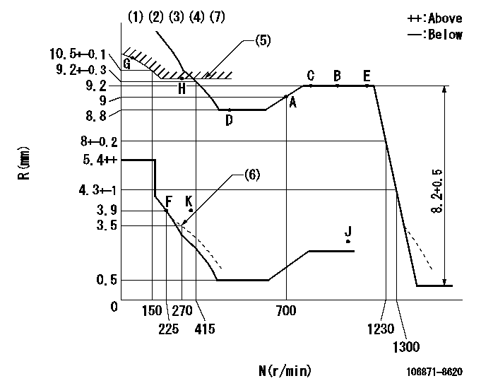
N:Pump speed
R:Rack position (mm)
(1)Lever ratio: RT
(2)Target shim dimension: TH
(3)Tolerance for racks not indicated: +-0.05mm.
(4)Supplied with torque spring not set.
(5)Excess fuel setting for starting: SXL (N = N1)
(6)Damper spring setting
(7)Set idle at point K (N = N2, R = R1) and confirm that the injection quantity at N = N3 at point J is Q1.
----------
RT=0.8 TH=2.8mm SXL=10+-0.1mm N1=300r/min N2=325r/min R1=3.9mm N3=1100r/min Q1=2mm3/st
----------
----------
RT=0.8 TH=2.8mm SXL=10+-0.1mm N1=300r/min N2=325r/min R1=3.9mm N3=1100r/min Q1=2mm3/st
----------
Speed control lever angle
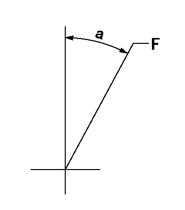
F:Full speed
----------
----------
a=(16deg)+-5deg
----------
----------
a=(16deg)+-5deg
0000000901
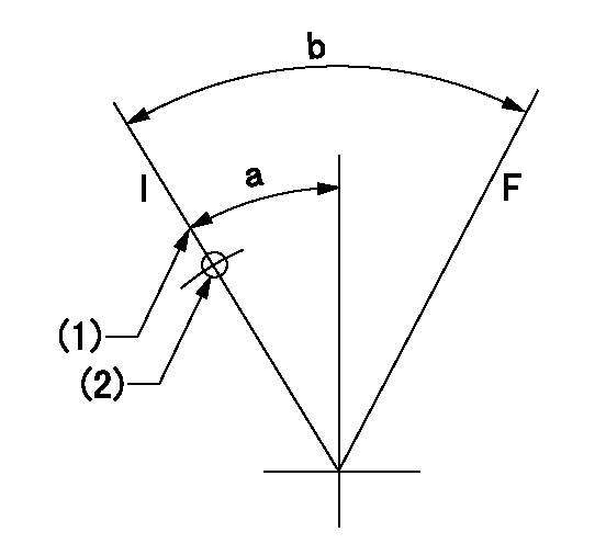
F:Full load
I:Idle
(1)Stopper bolt setting
(2)Use the hole at R = aa
----------
aa=42mm
----------
a=39deg+-5deg b=44deg+-3deg
----------
aa=42mm
----------
a=39deg+-5deg b=44deg+-3deg
Stop lever angle
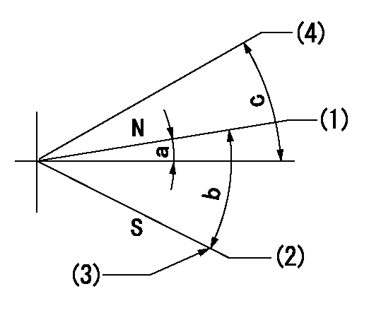
N:Engine manufacturer's normal use
S:Stop the pump.
(1)Rack position = aa
(2)Rack position bb
(3)Set the stopper bolt (apply red paint).
(4)Free (at delivery)
----------
aa=12mm bb=2.5-0.5mm
----------
a=1deg+-5deg b=27.5deg+-5deg c=(34deg)
----------
aa=12mm bb=2.5-0.5mm
----------
a=1deg+-5deg b=27.5deg+-5deg c=(34deg)
0000001501 RACK SENSOR
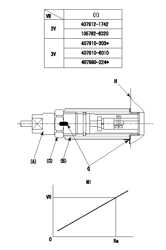
(VR) measurement voltage
(I) Part number of the control unit
(G) Apply red paint.
(H): End surface of the pump
1. Rack sensor adjustment (-0620)
(1)Fix the speed control lever at the full position
(2)Set the speed to N1 r/min.
(If the boost compensator is provided, apply boost pressure.)
(3)Adjust the bobbin (A) so that the rack sensor's output voltage is VR+-0.01.
(4)At that time, rack position must be Ra.
(5)Apply G at two places.
Connecting part between the joint (B) and the nut (F)
Connecting part between the joint (B) and the end surface of the pump (H)
----------
N1=1100r/min Ra=9.2mm
----------
----------
N1=1100r/min Ra=9.2mm
----------
Timing setting

(1)Pump vertical direction
(2)Coupling's key groove position at No 1 cylinder's beginning of injection
(3)-
(4)-
----------
----------
a=(80deg)
----------
----------
a=(80deg)
Information:
(1) Diameter of the surfaces (journals) for the camshaft bearings (new) ... 63.500 0.013 mm (2.5000 .0005 in) Bore in the five bearings for the camshaft (new) ... 63.589 0.038 mm (2.5035 .0015 in)Maximum permissible clearance between bearing and bearing surface (journal) (worn) ... 0.18 mm (.007 in)(2) Tight fit between the gear and camshaft ... 0.030 to 0.071 mm (.0012 to .0028 in) Maximum permissible temperature of the gear for installation on the camshaft (do not use a torch) ... 315°C (600°F)(3) End play for the camshaft ... 0.18 0.08 mm (.007 .003 in) Maximum permissible end play (worn) ... 0.51 mm (.020 in)(4) Width of thrust groove in camshaft (new) ... 9.14 0.05 mm (.360 .002 in) Diameter of thrust pin (new) ... 8.97 0.03 mm (.353 .001 in)Torque for thrust pin ... 48 7 N m (35 5 lb ft)(5) Height of camshaft lobes.To find lobe lift, use the procedure that follows:A. Measure camshaft lobe height (5).B. Measure base circle (7).C. Subtract base circle (Step B) from lobe height (Step A). The difference is actual lobe lift (6).D. Specified camshaft lobe lift (6) is: 9N5230 Camshaft used with roller lifters: a. Exhaust lobe ... 9.40 mm (.370 in) b. Intake lobe ... 9.33 mm (.367 in)2W4238 Camshaft used with flat face lifters: c. Exhaust lobe ... 9.40 mm (.370 in) d. Intake lobe ... 9.06 mm (.357 in)Maximum permissible difference between actual lobe lift (Step C) and specified lobe lift (Step D) is 0.25 mm (.010 in).
Camshaft Gear Assembly
View A-A(8) Distance from the end of 9N5771 Dowell to the face of gear ... 11.81 0.13 mm(.465 .005 in)
View B-B(9) Distance from the end of 5P4283 Dowel to the face of camshaft ... 2.00 0.25 mm(.079 .010 in)Camshaft Installation
For installation of camshaft, the timing mark on the camshaft gear tooth must be in alignment with the timing mark on the tooth space of the crankshaft gear.Intake Valve Timing
1. Check the No. 1 intake valve clearance with the engine stopped. The valve clearance must be 0.30 to 0.46 mm (.012 to .018 in). If the valve clearance is not in this range, adjust the clearance to 0.38 mm (.015 in).2. Mark Top Center Position of the crankshaft on the vibration damper or pulley.3. Use a dial indicator to measure the intake valve movement.4. Rotate the crankshaft in the direction of normal engine rotation. Stop when the intake valve is 1.91 mm (.075 in) off its seat in the opening sequence. At this point the crankshaft must be 10 2° After Top Center.
Have questions with 106871-8620?
Group cross 106871-8620 ZEXEL
Hino
Hino
106871-8620
9 400 618 287
220006930A
INJECTION-PUMP ASSEMBLY
F17E
F17E