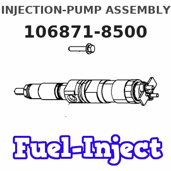
Information injection-pump assembly
BOSCH
9 400 618 277
9400618277
ZEXEL
106871-8500
1068718500
HINO
220006680A
220006680a

Rating:
Service parts 106871-8500 INJECTION-PUMP ASSEMBLY:
1.
_
7.
COUPLING PLATE
8.
_
9.
_
11.
Nozzle and Holder
23600-2230A
12.
Open Pre:MPa(Kqf/cm2)
17.7{180}/24.5{250}
15.
NOZZLE SET
Include in #1:
106871-8500
as INJECTION-PUMP ASSEMBLY
Cross reference number
Zexel num
Bosch num
Firm num
Name
106871-8500
9 400 618 277
220006680A HINO
INJECTION-PUMP ASSEMBLY
F17C A * K
F17C A * K
Information:
1. Disconnect the fuel priming pump fuel inlet line (1).2. Disconnect the fuel supply line.3. Remove the two mounting bolts (2) and remove the tachometer drive (4).4. Remove the two mounting bolts (3) and remove the fuel transfer pump.Install Fuel Transfer Pump
1. Position the fuel transfer pump on the engine and install the mounting bolts.2. Install the tachometer drive.3. Connect the fuel supply line.4. Connect the fuel priming pump fuel inlet line.5. Prime the fuel system and bleed off the air, with the fuel priming pump.Disassemble Fuel Transfer Pump
preparatory step: a) remove fuel transfer pump1. Remove the gear retaining nut (2), gear (3), and woodruff key.2. Remove the cage assembly (1).3. Remove the O-ring seals from the cage assembly. 4. Using tool (A), remove the bearing and lip-type seals from cage. 5. Remove the cover assembly (5).
Be careful not to damage mating surfaces of cover assembly and pump body.
6. Remove the seal from the cover assembly.7. Remove the gear (4), and gear and shaft assembly (6) from pump body. 8. Using tool (A), remove the bearing from pump body.Assemble Fuel Transfer Pump
1. Clean all parts thoroughly before assembling pump. 2. Using tool (A), install the bearing in pump body.3. Position the gear, and gear and shaft assembly in body. 4. Using tool (B), install the seal in the cover assembly.5. Apply a thin film of 8S6747 Liquid Gasket Material to face of body assembly.
Do not allow liquid gasket material to enter pump.
6. Install the cover assembly on pump body. After tightening cover assembly retaining bolts, the gear and shaft assembly must rotate freely. 7. Using tool (B), install the seals in the cage. Install the inner seal with lip of seal toward pump drive gear. Install the outer seal with lip toward pump body. 8. Using tool (A), install the bearing in the cage assembly.9. Install the O-ring seals on cage assembly.10. Lubricate the O-ring seals and lip-type seals with clean SAE 30 engine oil.11. Position the cage assembly on the gear and shaft assembly.12. Install the woodruff key, gear, and retaining nut. Tighten the retaining nut to 22 5 lb. ft. (3,0 0,7 mkg).concluding step: a) install fuel transfer pump
Have questions with 106871-8500?
Group cross 106871-8500 ZEXEL
Hino
106871-8500
9 400 618 277
220006680A
INJECTION-PUMP ASSEMBLY
F17C
F17C
