Information injection-pump assembly
BOSCH
9 400 618 273
9400618273
ZEXEL
106871-8450
1068718450
HINO
220006630A
220006630a
Rating:
Service parts 106871-8450 INJECTION-PUMP ASSEMBLY:
1.
_
7.
COUPLING PLATE
8.
_
9.
_
11.
Nozzle and Holder
23600-2230A
12.
Open Pre:MPa(Kqf/cm2)
17.7{180}/24.5{250}

15.
NOZZLE SET
Include in #1:
106871-8450
as INJECTION-PUMP ASSEMBLY
Cross reference number
BOSCH
9 400 618 273
9400618273
ZEXEL
106871-8450
1068718450
HINO
220006630A
220006630a
Zexel num
Bosch num
Firm num
Name
106871-8450
9 400 618 273
220006630A HINO
INJECTION-PUMP ASSEMBLY
F17C K
F17C K
Calibration Data:
Adjustment conditions
Test oil
1404 Test oil ISO4113 or {SAEJ967d}
1404 Test oil ISO4113 or {SAEJ967d}
Test oil temperature
degC
40
40
45
Nozzle and nozzle holder
105780-8140
Bosch type code
EF8511/9A
Nozzle
105780-0000
Bosch type code
DN12SD12T
Nozzle holder
105780-2080
Bosch type code
EF8511/9
Opening pressure
MPa
17.2
Opening pressure
kgf/cm2
175
Injection pipe
Outer diameter - inner diameter - length (mm) mm 8-3-600
Outer diameter - inner diameter - length (mm) mm 8-3-600
Overflow valve
134424-0820
Overflow valve opening pressure
kPa
127
107
147
Overflow valve opening pressure
kgf/cm2
1.3
1.1
1.5
Tester oil delivery pressure
kPa
157
157
157
Tester oil delivery pressure
kgf/cm2
1.6
1.6
1.6
Direction of rotation (viewed from drive side)
Right R
Right R
Injection timing adjustment
Direction of rotation (viewed from drive side)
Right R
Right R
Injection order
1-8-6-2-
7-5-4-3
Pre-stroke
mm
4.8
4.74
4.8
Beginning of injection position
Drive side NO.1
Drive side NO.1
Difference between angles 1
Cal 1-8 deg. 45 44.75 45.25
Cal 1-8 deg. 45 44.75 45.25
Difference between angles 2
Cal 1-6 deg. 90 89.75 90.25
Cal 1-6 deg. 90 89.75 90.25
Difference between angles 3
Cyl.1-2 deg. 135 134.75 135.25
Cyl.1-2 deg. 135 134.75 135.25
Difference between angles 4
Cal 1-7 deg. 180 179.75 180.25
Cal 1-7 deg. 180 179.75 180.25
Difference between angles 5
Cal 1-5 deg. 225 224.75 225.25
Cal 1-5 deg. 225 224.75 225.25
Difference between angles 6
Cal 1-4 deg. 270 269.75 270.25
Cal 1-4 deg. 270 269.75 270.25
Difference between angles 7
Cal 1-3 deg. 315 314.75 315.25
Cal 1-3 deg. 315 314.75 315.25
Injection quantity adjustment
Adjusting point
A
Rack position
9.8
Pump speed
r/min
700
700
700
Average injection quantity
mm3/st.
140.2
138.2
142.2
Max. variation between cylinders
%
0
-2
2
Basic
*
Fixing the lever
*
Injection quantity adjustment_02
Adjusting point
B
Rack position
10.1
Pump speed
r/min
1100
1100
1100
Average injection quantity
mm3/st.
136.8
130.8
142.8
Max. variation between cylinders
%
0
-4
4
Fixing the lever
*
Injection quantity adjustment_03
Adjusting point
C
Rack position
9.9
Pump speed
r/min
900
900
900
Average injection quantity
mm3/st.
138.4
135.4
141.4
Fixing the lever
*
Injection quantity adjustment_04
Adjusting point
D
Rack position
9.8
Pump speed
r/min
500
500
500
Average injection quantity
mm3/st.
143.8
140.8
146.8
Fixing the lever
*
Injection quantity adjustment_05
Adjusting point
E
Rack position
9.4
Pump speed
r/min
1200
1200
1200
Average injection quantity
mm3/st.
119.3
116.3
122.3
Fixing the lever
*
Injection quantity adjustment_06
Adjusting point
F
Rack position
4.2+-0.5
Pump speed
r/min
225
225
225
Average injection quantity
mm3/st.
9.1
6.1
12.1
Max. variation between cylinders
%
0
-15
15
Fixing the rack
*
Timer adjustment
Pump speed
r/min
900
Advance angle
deg.
1.7
1.4
2
Load
3/4
Timer adjustment_02
Pump speed
r/min
1060
Advance angle
deg.
4.75
4.45
5.05
Load
4/4
Remarks
Finish
Finish
Test data Ex:
Governor adjustment
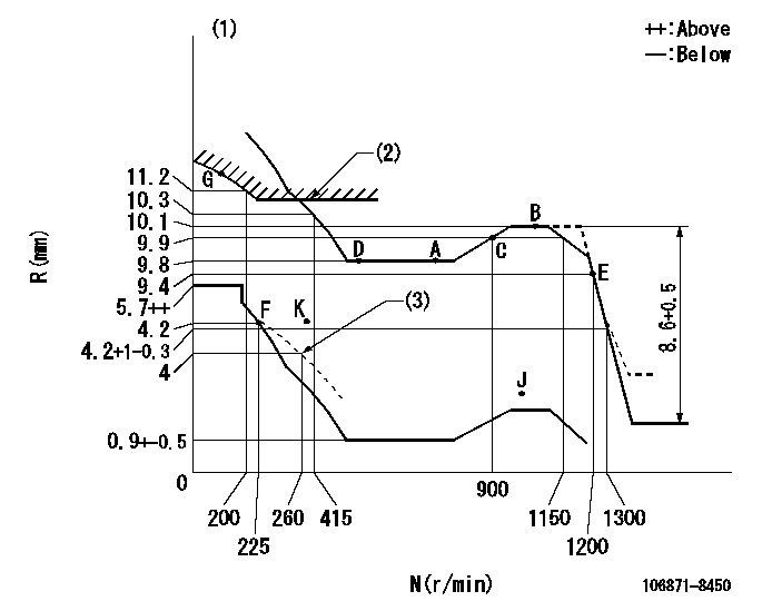
N:Pump speed
R:Rack position (mm)
(1)Tolerance for racks not indicated: +-0.05mm.
(2)Excess fuel setting for starting: SXL (N = N1)
(3)Set the damper spring (after setting the idle spring).
----------
SXL=11+-0.1mm N1=300r/min
----------
----------
SXL=11+-0.1mm N1=300r/min
----------
Speed control lever angle

F:Full speed
----------
----------
a=14deg+-5deg
----------
----------
a=14deg+-5deg
0000000901

F:Full load
I:Idle
(1)Use the hole at R = aa
(2)Stopper bolt setting
----------
aa=42mm
----------
a=39deg+-5deg b=46deg+-3deg
----------
aa=42mm
----------
a=39deg+-5deg b=46deg+-3deg
Stop lever angle
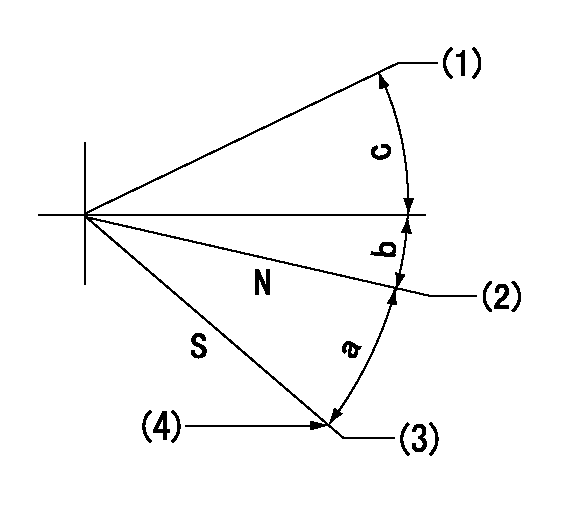
N:Engine manufacturer's normal use
S:Stop the pump.
(1)Free (at shipping)
(2)Rack position = aa
(3)Rack position bb
(4)Set the stopper bolt (apply red paint).
----------
aa=12mm bb=3mm
----------
a=26deg+-5deg b=5deg+-5deg c=(28deg)
----------
aa=12mm bb=3mm
----------
a=26deg+-5deg b=5deg+-5deg c=(28deg)
0000001501 RACK SENSOR

(VR) measurement voltage
(I) Part number of the control unit
(G) Apply red paint.
(H): End surface of the pump
1. Rack sensor adjustment (-0620)
(1)Fix the speed control lever at the full position
(2)Set the speed to N1 r/min.
(If the boost compensator is provided, apply boost pressure.)
(3)Adjust the bobbin (A) so that the rack sensor's output voltage is VR+-0.01.
(4)At that time, rack position must be Ra.
(5)Apply G at two places.
Connecting part between the joint (B) and the nut (F)
Connecting part between the joint (B) and the end surface of the pump (H)
----------
N1=1070r/min Ra=10.1mm
----------
----------
N1=1070r/min Ra=10.1mm
----------
Timing setting

(1)Pump vertical direction
(2)Coupling's key groove position at No 1 cylinder's beginning of injection
(3)-
(4)-
----------
----------
a=(80deg)
----------
----------
a=(80deg)
Information:
Lubrication For A Rebuilt Engine
It is very important for a rebuilt engine to have "adequate" (needed) lubrication during the first seconds of operation. A "dry start" (without needed lubrication) on a rebuilt engine can cause bearing damage.When an engine is rebuilt with new parts, oil is put on each part as it is installed. This is generally enough lubrication for engine start-up. However, this lubrication may not be enough or may be lost if the rebuilt engine is placed in storage for any length of time.When a factory assembled short block assembly is installed, the oil used at the factory has to give this needed lubrication. However, the factory oil application can flow off the parts in a short block during storage or shipment. As a result, the parts in a rebuilt engine will not have "adequate" lubrication at start-up.To prevent the possibility of a "dry start" and bearing damage during the first seconds of running, use the 1P540 Flow Checking Tool Group, and shop air pressure to pressure lubricate (fill the main oil passage with oil under pressure) all rebuilt engines.Procedure for Pressure Lubrication
1. Clean the tank of the 1P540 Flow Checking Tool Group thoroughly, and set the pressure regulator to 35 5 psi (240 35 kPa).
Air pressure should not be more than 50 psi (345 kPa) at any time.
2. Put approximately one gallon of engine oil in the tank.
PRESSURE LUBRICATION (Using the 1P540 Flow Checking Tool Group)3. Connect the tooling to the engine as shown. The tap shown is connected to the main oil passage.4. Add air pressure to the tank, with the regulator set at 35 5 psi (240 35 kPa). Although the tank does have a hand pump, it is difficult to get enough air pressure to do the job with the hand pump. Therefore, use of shop air is recommended.5. Let the one gallon of engine oil flow into the oil passage under pressure.When filling the crankcase, put in one gallon of oil less than the recommendation in the Lubrication and Maintenance Guides, if engine has received this pressure lubrication application. Also, if the engine is not going to be used for a long time, do the above procedure again before the first starting.If shop air is not available for charging the tank, the hand pump may be used to get the minimum required pressure.
Do not use the same 1P540 Flow Checking Tool Group for both "pressure lubrication application" and for checking fuel flow. Incorrect cleaning is probable if the tool is used for both fuel and lube oil. Even a minute amount of dirt in the fuel system can cause fuel nozzle failure.
Dynamometer Test Precaution
To avoid possible engine damage while testing on a dynamometer, the thermostats must be installed and the shunt line connected as shown.
SHUNT LINE CONNECTED TO ENGINEInitial Operation After Engine Reconditioning
The quality of oil control components used in Caterpillar engines is such that, following engine reconditioning (with Caterpillar Service Parts), only an initial operational check
Have questions with 106871-8450?
Group cross 106871-8450 ZEXEL
Hino
106871-8450
9 400 618 273
220006630A
INJECTION-PUMP ASSEMBLY
F17C
F17C