Information injection-pump assembly
BOSCH
9 400 618 270
9400618270
ZEXEL
106871-8420
1068718420
HINO
220006600A
220006600a

Rating:
Service parts 106871-8420 INJECTION-PUMP ASSEMBLY:
1.
_
7.
COUPLING PLATE
8.
_
9.
_
11.
Nozzle and Holder
23600-2230A
12.
Open Pre:MPa(Kqf/cm2)
17.7{180}/24.5{250}

15.
NOZZLE SET
Include in #1:
106871-8420
as INJECTION-PUMP ASSEMBLY
Cross reference number
BOSCH
9 400 618 270
9400618270
ZEXEL
106871-8420
1068718420
HINO
220006600A
220006600a
Zexel num
Bosch num
Firm num
Name
106871-8420
9 400 618 270
220006600A HINO
INJECTION-PUMP ASSEMBLY
F17C A * K 14CD PE8P PE
F17C A * K 14CD PE8P PE
Calibration Data:
Adjustment conditions
Test oil
1404 Test oil ISO4113 or {SAEJ967d}
1404 Test oil ISO4113 or {SAEJ967d}
Test oil temperature
degC
40
40
45
Nozzle and nozzle holder
105780-8140
Bosch type code
EF8511/9A
Nozzle
105780-0000
Bosch type code
DN12SD12T
Nozzle holder
105780-2080
Bosch type code
EF8511/9
Opening pressure
MPa
17.2
Opening pressure
kgf/cm2
175
Injection pipe
Outer diameter - inner diameter - length (mm) mm 8-3-600
Outer diameter - inner diameter - length (mm) mm 8-3-600
Overflow valve
134424-0820
Overflow valve opening pressure
kPa
127
107
147
Overflow valve opening pressure
kgf/cm2
1.3
1.1
1.5
Tester oil delivery pressure
kPa
157
157
157
Tester oil delivery pressure
kgf/cm2
1.6
1.6
1.6
Direction of rotation (viewed from drive side)
Right R
Right R
Injection timing adjustment
Direction of rotation (viewed from drive side)
Right R
Right R
Injection order
1-8-6-2-
7-5-4-3
Pre-stroke
mm
4.8
4.74
4.8
Beginning of injection position
Drive side NO.1
Drive side NO.1
Difference between angles 1
Cal 1-8 deg. 45 44.75 45.25
Cal 1-8 deg. 45 44.75 45.25
Difference between angles 2
Cal 1-6 deg. 90 89.75 90.25
Cal 1-6 deg. 90 89.75 90.25
Difference between angles 3
Cyl.1-2 deg. 135 134.75 135.25
Cyl.1-2 deg. 135 134.75 135.25
Difference between angles 4
Cal 1-7 deg. 180 179.75 180.25
Cal 1-7 deg. 180 179.75 180.25
Difference between angles 5
Cal 1-5 deg. 225 224.75 225.25
Cal 1-5 deg. 225 224.75 225.25
Difference between angles 6
Cal 1-4 deg. 270 269.75 270.25
Cal 1-4 deg. 270 269.75 270.25
Difference between angles 7
Cal 1-3 deg. 315 314.75 315.25
Cal 1-3 deg. 315 314.75 315.25
Injection quantity adjustment
Adjusting point
A
Rack position
9.8
Pump speed
r/min
700
700
700
Average injection quantity
mm3/st.
140.2
138.2
142.2
Max. variation between cylinders
%
0
-2
2
Basic
*
Fixing the lever
*
Injection quantity adjustment_02
Adjusting point
B
Rack position
10.1
Pump speed
r/min
1100
1100
1100
Average injection quantity
mm3/st.
136.8
130.8
142.8
Max. variation between cylinders
%
0
-4
4
Fixing the lever
*
Injection quantity adjustment_03
Adjusting point
C
Rack position
9.9
Pump speed
r/min
900
900
900
Average injection quantity
mm3/st.
138.4
135.4
141.4
Fixing the lever
*
Injection quantity adjustment_04
Adjusting point
D
Rack position
9.8
Pump speed
r/min
500
500
500
Average injection quantity
mm3/st.
143.8
140.8
146.8
Fixing the lever
*
Injection quantity adjustment_05
Adjusting point
E
Rack position
9.4
Pump speed
r/min
1200
1200
1200
Average injection quantity
mm3/st.
119.3
116.3
122.3
Fixing the lever
*
Injection quantity adjustment_06
Adjusting point
F
Rack position
4.2+-0.5
Pump speed
r/min
225
225
225
Average injection quantity
mm3/st.
9.1
6.1
12.1
Max. variation between cylinders
%
0
-15
15
Fixing the rack
*
Timer adjustment
Pump speed
r/min
900
Advance angle
deg.
1.7
1.4
2
Load
3/4
Timer adjustment_02
Pump speed
r/min
1060
Advance angle
deg.
4.75
4.45
5.05
Load
4/4
Remarks
Finish
Finish
Test data Ex:
Governor adjustment
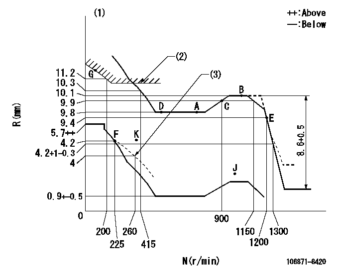
N:Pump speed
R:Rack position (mm)
(1)Tolerance for racks not indicated: +-0.05mm.
(2)Excess fuel setting for starting: SXL
(3)Set the damper spring (after setting the idle spring).
----------
SXL=11+-0.1mm
----------
----------
SXL=11+-0.1mm
----------
Speed control lever angle

F:Full speed
----------
----------
a=14deg+-5deg
----------
----------
a=14deg+-5deg
0000000901

F:Full load
I:Idle
(1)Stopper bolt setting
(2)Use the hole at R = aa
----------
aa=42mm
----------
a=39deg+-5deg b=46deg+-3deg
----------
aa=42mm
----------
a=39deg+-5deg b=46deg+-3deg
Stop lever angle

N:Pump normal
S:Stop the pump.
----------
----------
a=10deg+-5deg b=64deg+-5deg
----------
----------
a=10deg+-5deg b=64deg+-5deg
0000001501 RACK SENSOR

(VR) measurement voltage
(I) Part number of the control unit
(G) Apply red paint.
(H): End surface of the pump
1. Rack sensor adjustment (-0620)
(1)Fix the speed control lever at the full position
(2)Set the speed to N1 r/min.
(If the boost compensator is provided, apply boost pressure.)
(3)Adjust the bobbin (A) so that the rack sensor's output voltage is VR+-0.01.
(4)At that time, rack position must be Ra.
(5)Apply G at two places.
Connecting part between the joint (B) and the nut (F)
Connecting part between the joint (B) and the end surface of the pump (H)
----------
N1=1070r/min Ra=10.1mm
----------
----------
N1=1070r/min Ra=10.1mm
----------
Timing setting

(1)Pump vertical direction
(2)Coupling's key groove position at No 1 cylinder's beginning of injection
(3)-
(4)-
----------
----------
a=(80deg)
----------
----------
a=(80deg)
Information:
Connecting Rod
Use the 2H6782 Connecting Rod Boring Machine to recondition connecting rods and to check for connecting rod distortion. The 5P2009 Rework Group is available for the 2H6782 Connecting Rod Boring Machine. To install the rework group see Special Instruction GMG02394.Press a new piston pin bushing into the connecting rod. Assemble new rod bearings and the expansion sleeve. Tighten rod bolt nuts in the following step sequence.1. Put crankcase oil on bolt threads and seating faces of cap and nut.2. Tighten both nuts to 30 3 lb. ft. (40 4 N m).3. Put a mark on each nut and cap.4. Tighten each nut 60° from the mark.Clean spindle and slide the expansion sleeve and connecting rod into place. Install and tighten nut hand tight.Adjust the carrier to the distance between center of the bores, [center-to-center distance is 7.900 .001 in. (200.66 0.03 mm)]. Position the locating rods .25 in. (6.4 mm) from the connecting rod. Install front bushing in bracket and insert locating arbor through front bushing. Slide the centering sleeve over the end of the locating arbor. Slide the locating arbor through the rear bushing, centering sleeve, and into the connecting rod. Tighten knobs until locating rods lightly contact the connecting rod. Lock the locating rods and carrier.To check connecting rod distortion, slide locating arbor in and out of rear bushing. If the locating arbor does not slide freely, recheck horizontal location. If the locating arbor still binds, loosen the carrier clamp and raise or lower the carrier until the locating arbor slides freely. Read the vernier scale and note the variation from the nominal dimension. If the variation exceeds .010 in. (0.25 mm) the rod is distorted and should be replaced. Mark replacement rods for cylinder identification on bearing tab slot side of rod and cap.With the center-to-center distance set to the nominal dimension, set tool in boring bar and insert the boring bar and front bushing. Connect boring bar to the feed mechanism and engage the feed lever. Install the hand crank or an electric drill and flexible adapter and bore the bushing. Use a slow feed rate. Check the bore size. The size is 1.5010 .0003 in. (48.125 0.008 mm). A 5P2050 Connecting Rod Checking Fixture is available for checking connecting rods. For instructions for the use of the checking fixture see Special Instruction SMHS7366.Install connecting rod into piston with boss on rod on same side as crater in piston crown.
CONNECTING ROD AND PISTONWhen installing connecting rod and piston assemblies, inspect the threads of the rod bolts and nuts for damage. The contact surface of the nuts must be flat and free from damage. Damaged parts must be replaced.
Have questions with 106871-8420?
Group cross 106871-8420 ZEXEL
Hino
106871-8420
9 400 618 270
220006600A
INJECTION-PUMP ASSEMBLY
F17C
F17C