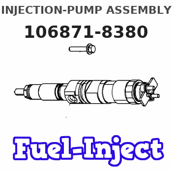
Information injection-pump assembly
BOSCH
9 400 618 267
9400618267
ZEXEL
106871-8380
1068718380
HINO
220006560A
220006560a
Rating:
Service parts 106871-8380 INJECTION-PUMP ASSEMBLY:
1.
_
7.
COUPLING PLATE
8.
_
9.
_
11.
Nozzle and Holder
23600-2230A
12.
Open Pre:MPa(Kqf/cm2)
17.7{180}/24.5{250}

15.
NOZZLE SET
Include in #1:
106871-8380
as INJECTION-PUMP ASSEMBLY
Cross reference number
BOSCH
9 400 618 267
9400618267
ZEXEL
106871-8380
1068718380
HINO
220006560A
220006560a
Zexel num
Bosch num
Firm num
Name
106871-8380
9 400 618 267
220006560A HINO
INJECTION-PUMP ASSEMBLY
F17C K
F17C K
Calibration Data:
Adjustment conditions
Test oil
1404 Test oil ISO4113 or {SAEJ967d}
1404 Test oil ISO4113 or {SAEJ967d}
Test oil temperature
degC
40
40
45
Nozzle and nozzle holder
105780-8140
Bosch type code
EF8511/9A
Nozzle
105780-0000
Bosch type code
DN12SD12T
Nozzle holder
105780-2080
Bosch type code
EF8511/9
Opening pressure
MPa
17.2
Opening pressure
kgf/cm2
175
Injection pipe
Outer diameter - inner diameter - length (mm) mm 8-3-600
Outer diameter - inner diameter - length (mm) mm 8-3-600
Overflow valve
134424-0820
Overflow valve opening pressure
kPa
127
107
147
Overflow valve opening pressure
kgf/cm2
1.3
1.1
1.5
Tester oil delivery pressure
kPa
157
157
157
Tester oil delivery pressure
kgf/cm2
1.6
1.6
1.6
Direction of rotation (viewed from drive side)
Right R
Right R
Injection timing adjustment
Direction of rotation (viewed from drive side)
Right R
Right R
Injection order
1-8-6-2-
7-5-4-3
Pre-stroke
mm
4.8
4.74
4.8
Rack position
Point A R=A
Point A R=A
Beginning of injection position
Drive side NO.1
Drive side NO.1
Difference between angles 1
Cal 1-8 deg. 45 44.75 45.25
Cal 1-8 deg. 45 44.75 45.25
Difference between angles 2
Cal 1-6 deg. 90 89.75 90.25
Cal 1-6 deg. 90 89.75 90.25
Difference between angles 3
Cyl.1-2 deg. 135 134.75 135.25
Cyl.1-2 deg. 135 134.75 135.25
Difference between angles 4
Cal 1-7 deg. 180 179.75 180.25
Cal 1-7 deg. 180 179.75 180.25
Difference between angles 5
Cal 1-5 deg. 225 224.75 225.25
Cal 1-5 deg. 225 224.75 225.25
Difference between angles 6
Cal 1-4 deg. 270 269.75 270.25
Cal 1-4 deg. 270 269.75 270.25
Difference between angles 7
Cal 1-3 deg. 315 314.75 315.25
Cal 1-3 deg. 315 314.75 315.25
Injection quantity adjustment
Adjusting point
A
Rack position
9.8
Pump speed
r/min
700
700
700
Average injection quantity
mm3/st.
140.2
138.2
142.2
Max. variation between cylinders
%
0
-2
2
Basic
*
Fixing the lever
*
Injection quantity adjustment_02
Adjusting point
B
Rack position
10.1
Pump speed
r/min
1100
1100
1100
Average injection quantity
mm3/st.
136.8
130.8
142.8
Max. variation between cylinders
%
0
-4
4
Fixing the lever
*
Injection quantity adjustment_03
Adjusting point
C
Rack position
9.9
Pump speed
r/min
900
900
900
Average injection quantity
mm3/st.
138.4
135.4
141.4
Fixing the lever
*
Injection quantity adjustment_04
Adjusting point
D
Rack position
9.8
Pump speed
r/min
500
500
500
Average injection quantity
mm3/st.
143.8
140.8
146.8
Fixing the lever
*
Injection quantity adjustment_05
Adjusting point
E
Rack position
9.4
Pump speed
r/min
1200
1200
1200
Average injection quantity
mm3/st.
119.3
116.3
122.3
Fixing the lever
*
Injection quantity adjustment_06
Adjusting point
F
Rack position
4.9+-0.5
Pump speed
r/min
225
225
225
Average injection quantity
mm3/st.
9.1
6.1
12.1
Max. variation between cylinders
%
0
-15
15
Fixing the rack
*
Test data Ex:
Governor adjustment
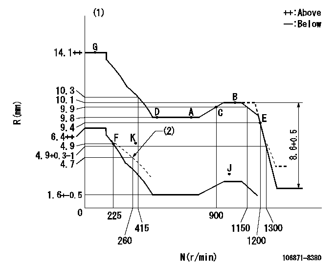
N:Pump speed
R:Rack position (mm)
(1)Tolerance for racks not indicated: +-0.05mm.
(2)Set the damper spring (after setting the idle spring).
----------
----------
----------
----------
Timer adjustment
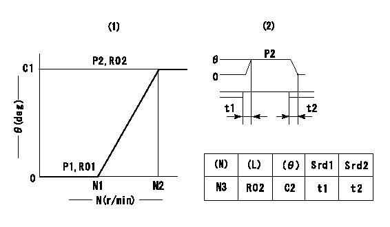
(1)Adjusting range
(2)Step response time
(N): Speed of the pump
(L): Load
(theta) Advance angle
(Srd1) Step response time 1
(Srd2) Step response time 2
1. Adjusting conditions for the variable timer
(1)Adjust the clearance between the pickup and the protrusion to L.
----------
L=1-0.2mm N3=800r/min C2=(7)deg t1=2--sec. t2=2--sec.
----------
N1=950+-50r/min N2=1500r/min P1=0kPa(0kgf/cm2) P2=392kPa(4kgf/cm2) C1=7+-0.3deg R01=0/4load R02=4/4load
----------
L=1-0.2mm N3=800r/min C2=(7)deg t1=2--sec. t2=2--sec.
----------
N1=950+-50r/min N2=1500r/min P1=0kPa(0kgf/cm2) P2=392kPa(4kgf/cm2) C1=7+-0.3deg R01=0/4load R02=4/4load
Speed control lever angle

F:Full speed
----------
----------
a=14deg+-5deg
----------
----------
a=14deg+-5deg
0000000901

F:Full load
I:Idle
(1)Use the hole at R = aa
(2)Stopper bolt setting
----------
aa=42mm
----------
a=39deg+-5deg b=44deg+-3deg
----------
aa=42mm
----------
a=39deg+-5deg b=44deg+-3deg
Stop lever angle

N:Pump normal
S:Stop the pump.
----------
----------
a=10deg+-5deg b=64deg+-5deg
----------
----------
a=10deg+-5deg b=64deg+-5deg
0000001501 RACK SENSOR

(VR) measurement voltage
(I) Part number of the control unit
(G) Apply red paint.
(H): End surface of the pump
1. Rack sensor adjustment (-0620)
(1)Fix the speed control lever at the full position
(2)Set the speed to N1 r/min.
(If the boost compensator is provided, apply boost pressure.)
(3)Adjust the bobbin (A) so that the rack sensor's output voltage is VR+-0.01.
(4)At that time, rack position must be Ra.
(5)Apply G at two places.
Connecting part between the joint (B) and the nut (F)
Connecting part between the joint (B) and the end surface of the pump (H)
----------
N1=1070r/min Ra=10.1mm
----------
----------
N1=1070r/min Ra=10.1mm
----------
Timing setting

(1)Pump vertical direction
(2)Coupling's key groove position at No 1 cylinder's beginning of injection
(3)-
(4)-
----------
----------
a=(80deg)
----------
----------
a=(80deg)
Information:
CRANKSHAFT
1. Bolts and washers (ten each). 2. Main bearing caps (five). 3. Crankshaft.2. Remove the main bearing caps (2) and lower halves of crankshaft main bearings.3. Attach a hoist and sling to the crankshaft (3). Remove the crankshaft, the weight is approx. 102 lbs. (46.3 kg).
REMOVING CRANKSHAFT4. Remove the upper halves of crankshaft main bearings.Install Crankshaft
1. Install the upper halves of main bearings. Lubricate the upper halves with clean engine oil (SAE 30).2. Attach a hoist and sling to the crankshaft. Position crankshaft in cylinder block. If camshaft is in the cylinder block, align timing mark on crankshaft gear with timing mark on camshaft gear.3. Lubricate lower halves of main bearings with clean engine oil (SAE 30). Install main bearing caps so number on cap corresponds with number on saddle of cylinder block. Both numbers must be on same side of cylinder block.4. Put engine oil on the threads of the bolts and the face of the washers and install the bolts into the cylinder block.
Do not rotate the crankshaft until all main bearing cap bolts have been tightened.
5. For 1140 (36B1-36B1923), 1145 (97B1-97B6154), 1150 (96B1-96B6580), 1160 (95B1-95B13691) Engines, tighten the bolts for the main bearing caps in the number sequence shown to a first torque of 60 15 lb. ft. (8.3 2.1 mkg). Tighten all bolts in the number sequence shown (hand torque only) to a last torque of 175 10 lb. ft. (24.2 1.4 mkg).6. For 1140 (36B1924-Up), 1145 (97B6155-Up), 1150 (96B6581-Up), 1160 (95B13692-Up) Engines, tighten the bolts for the main bearing caps in the number sequence shown to a first torque of 30 3 lb. ft. (4.1 0.4 mkg). Put a mark on each bolt and cap and tighten, in the number sequence shown, an added 120° 5° from the mark.
BOLT TIGHTENING SEQUENCE7. Check crankshaft end play. End play with new bearings should be .006 .003 in. (0.15 0.08 mm). Maximum allowable end play is .012 in. (0.30 mm).
Have questions with 106871-8380?
Group cross 106871-8380 ZEXEL
Hino
Hino
106871-8380
9 400 618 267
220006560A
INJECTION-PUMP ASSEMBLY
F17C
F17C