Information injection-pump assembly
BOSCH
9 400 612 052
9400612052
ZEXEL
106871-8310
1068718310
HINO
220203400A
220203400a
Rating:
Service parts 106871-8310 INJECTION-PUMP ASSEMBLY:
1.
_

7.
COUPLING PLATE
8.
_
9.
_
11.
Nozzle and Holder
23600-2110A
12.
Open Pre:MPa(Kqf/cm2)
21.6{220}
15.
NOZZLE SET
Include in #1:
106871-8310
as INJECTION-PUMP ASSEMBLY
Cross reference number
BOSCH
9 400 612 052
9400612052
ZEXEL
106871-8310
1068718310
HINO
220203400A
220203400a
Zexel num
Bosch num
Firm num
Name
106871-8310
9 400 612 052
220203400A HINO
INJECTION-PUMP ASSEMBLY
EF750T K 14CD INJECTION PUMP ASSY PE8P PE
EF750T K 14CD INJECTION PUMP ASSY PE8P PE
Calibration Data:
Adjustment conditions
Test oil
1404 Test oil ISO4113 or {SAEJ967d}
1404 Test oil ISO4113 or {SAEJ967d}
Test oil temperature
degC
40
40
45
Nozzle and nozzle holder
105780-8140
Bosch type code
EF8511/9A
Nozzle
105780-0000
Bosch type code
DN12SD12T
Nozzle holder
105780-2080
Bosch type code
EF8511/9
Opening pressure
MPa
17.2
Opening pressure
kgf/cm2
175
Injection pipe
Outer diameter - inner diameter - length (mm) mm 8-3-600
Outer diameter - inner diameter - length (mm) mm 8-3-600
Overflow valve
134424-0820
Overflow valve opening pressure
kPa
127
107
147
Overflow valve opening pressure
kgf/cm2
1.3
1.1
1.5
Tester oil delivery pressure
kPa
157
157
157
Tester oil delivery pressure
kgf/cm2
1.6
1.6
1.6
Direction of rotation (viewed from drive side)
Right R
Right R
Injection timing adjustment
Direction of rotation (viewed from drive side)
Right R
Right R
Injection order
1-8-6-2-
7-5-4-3
Pre-stroke
mm
4.5
4.44
4.5
Beginning of injection position
Drive side NO.1
Drive side NO.1
Difference between angles 1
Cal 1-8 deg. 45 44.75 45.25
Cal 1-8 deg. 45 44.75 45.25
Difference between angles 2
Cal 1-6 deg. 90 89.75 90.25
Cal 1-6 deg. 90 89.75 90.25
Difference between angles 3
Cyl.1-2 deg. 135 134.75 135.25
Cyl.1-2 deg. 135 134.75 135.25
Difference between angles 4
Cal 1-7 deg. 180 179.75 180.25
Cal 1-7 deg. 180 179.75 180.25
Difference between angles 5
Cal 1-5 deg. 225 224.75 225.25
Cal 1-5 deg. 225 224.75 225.25
Difference between angles 6
Cal 1-4 deg. 270 269.75 270.25
Cal 1-4 deg. 270 269.75 270.25
Difference between angles 7
Cal 1-3 deg. 315 314.75 315.25
Cal 1-3 deg. 315 314.75 315.25
Injection quantity adjustment
Adjusting point
A
Rack position
9
Pump speed
r/min
1100
1100
1100
Average injection quantity
mm3/st.
145.3
143.3
147.3
Max. variation between cylinders
%
0
-2
2
Basic
*
Fixing the lever
*
Injection quantity adjustment_02
Adjusting point
B
Rack position
10.3
Pump speed
r/min
650
650
650
Average injection quantity
mm3/st.
171.4
165.4
177.4
Max. variation between cylinders
%
0
-4
4
Fixing the lever
*
Injection quantity adjustment_03
Adjusting point
C
Rack position
5.6+-0.5
Pump speed
r/min
250
250
250
Average injection quantity
mm3/st.
18.4
15.4
21.4
Max. variation between cylinders
%
0
-15
15
Fixing the rack
*
Injection quantity adjustment_04
Adjusting point
D
Rack position
-
Pump speed
r/min
100
100
100
Average injection quantity
mm3/st.
172
172
192
Fixing the lever
*
Rack limit
*
Timer adjustment
Pump speed
r/min
880--
Advance angle
deg.
0
0
0
Remarks
Start
Start
Timer adjustment_02
Pump speed
r/min
830
Advance angle
deg.
0.5
Timer adjustment_03
Pump speed
r/min
1000
Advance angle
deg.
2.5
2.2
2.8
Remarks
Finish
Finish
Test data Ex:
Governor adjustment
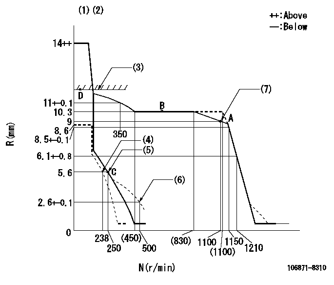
N:Pump speed
R:Rack position (mm)
(1)Target notch: K
(2)Tolerance for racks not indicated: +-0.05mm.
(3)RACK LIMIT
(4)Set idle sub-spring
(5)Main spring setting
(6)Damper spring setting
(7)Set the torque spring.
----------
K=11
----------
----------
K=11
----------
Speed control lever angle
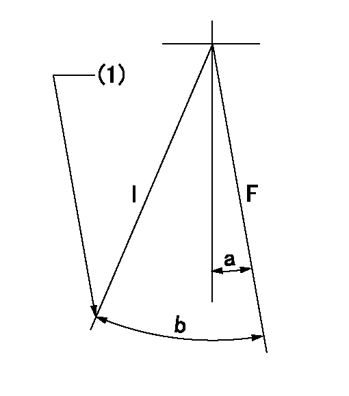
F:Full speed
I:Idle
(1)Stopper bolt setting
----------
----------
a=9deg+-5deg b=23deg+-5deg
----------
----------
a=9deg+-5deg b=23deg+-5deg
Stop lever angle
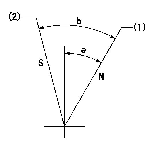
N:Pump normal
S:Stop the pump.
(1)Normal
(2)Speed = aa, rack position = bb or less (idle rack - cc)
----------
aa=0r/min bb=5.1mm cc=0.5mm
----------
a=26.5deg+-5deg b=53deg+-5deg
----------
aa=0r/min bb=5.1mm cc=0.5mm
----------
a=26.5deg+-5deg b=53deg+-5deg
Timing setting

(1)Pump vertical direction
(2)Coupling's key groove position at No 1 cylinder's beginning of injection
(3)-
(4)-
----------
----------
a=(85deg)
----------
----------
a=(85deg)
Information:
WRENCH INSTALLED
1. 8S2243 Wrench. 2. Protective cap. 3. Retaining bushing.c. Install extractor (4).d. Remove retaining bushing (3) and wrench (1).e. Remove the seal and lift fuel injection pump (5) out of the housing. Keep components together and identified as to location.4. Remove rack (7) and rack bumper spring (6).
REMOVING PUMP
4. 8S2244 Extractor. 5. Fuel injection pump.
REMOVING RACK
6. Rack bumper spring. 7. Rack.5. Use magnet (8) to remove lifters (9). Identify lifters (9) and keep them with their respective fuel injection pumps.
REMOVING LIFTERS
8. 8S2293 Magnet. 9. Lifter.6. Remove the camshaft gear assembly retaining bolt (11) and lock. Remove plate assembly (10).
REMOVING PLATE ASSEMBLY
10. Plate assembly. 11. Bolt.7. Remove camshaft gear assembly (12) from camshaft (13).
REMOVING GEAR ASSEMBLY
12. Gear assembly. 13. Camshaft.
REMOVING BOLTS
14. Lock. 15. Bolts.8. Remove bolts (15) and lock (14).9. Remove camshaft retaining plate (16).
REMOVING RETAINING PLATE
16. Retaining plate.10. Remove camshaft (13).
REMOVING CAMSHAFT
13. Camshaft.11. Use camshaft bearing removal and installation group (17) to remove the camshaft bearings from the fuel injection pump housing.
REMOVING BEARINGS
17. 8S2241 Camshaft Bearing Removal and Installation Group.Assemble Fuel Injection Pump Housing
1. Use camshaft bearing removal and installation group (17) to install the camshaft bearings in the fuel injection pump housing. The camshaft bearings must be installed with the oil holes in the bearings in line with the oil hole in the housing. The front and rear bearings must be line bored after installation. To align oil holes and line bore the bearings, See Special Instruction (GMG00672).
INSTALLING BEARINGS
17. 8S2241 Camshaft Bearing Removal and Installation Group.2. Put clean engine oil (SAE 30) on the camshaft and install camshaft (13) in the fuel injection pump housing.
INSTALLING CAMSHAFT
13. Camshaft.3. Install the camshaft retaining plate (16).4. Install lock (14) and bolts (15).
INSTALLING RETAINING PLATE
16. Retaining plate.
INSTALLING BOLTS
14. Lock. 15. Bolts.5. Install camshaft gear assembly (12) on camshaft (13).
INSTALLING GEAR ASSEMBLY
12. Gear assembly. 13. Camshaft.6. Install plate assembly (10), retaining bolt (11), and lock.
INSTALLING PLATE ASSEMBLY
10. Plate assembly. 11. Bolt. Be sure to put the spacer on bolt (11).7. Use magnet (8) to install lifters (9). The lifters (9) must be installed in the same location from which they were removed.
INSTALLING LIFTERS
8. 8S2293 Magnet. 9. Lifters.8. Lubricate the rack with clean fuel oil. Install rack (7) with timing pin slot in rack toward front of the housing. Install rack bumper spring (6) so the large diameter of the bumper spring will be against the housing. If new lifters and pumps are to be installed it will be necessary to check and/or adjust the fuel pump timing dimension. See FUEL PUMP TIMING DIMENSION SETTING-OFF ENGINE in TESTING AND ADJUSTING section of the Service Manual.
INSTALLING RACK
6. Rack bumper spring. 7. Rack.9. Remove bolts (19) and rack cover (18).
RACK COVER
18. Rack cover. 19. Bolts.
TIMING PIN INSTALLED
20. Slot in rack. 21. 8S2291 or FT887 Timing Pin.10. The rack must be centered to install the fuel injection pumps. To center the rack, pull the rack toward the governor end of the housing until centering slot (20) in the rack is under the centering pin hole.
Have questions with 106871-8310?
Group cross 106871-8310 ZEXEL
Hino
106871-8310
9 400 612 052
220203400A
INJECTION-PUMP ASSEMBLY
EF750T
EF750T