Information injection-pump assembly
ZEXEL
106871-7560
1068717560
MITSUBISHI
ME090613
me090613
Rating:
Cross reference number
ZEXEL
106871-7560
1068717560
MITSUBISHI
ME090613
me090613
Zexel num
Bosch num
Firm num
Name
Calibration Data:
Adjustment conditions
Test oil
1404 Test oil ISO4113 or {SAEJ967d}
1404 Test oil ISO4113 or {SAEJ967d}
Test oil temperature
degC
40
40
45
Nozzle and nozzle holder
105780-8140
Bosch type code
EF8511/9A
Nozzle
105780-0000
Bosch type code
DN12SD12T
Nozzle holder
105780-2080
Bosch type code
EF8511/9
Opening pressure
MPa
17.2
Opening pressure
kgf/cm2
175
Injection pipe
Outer diameter - inner diameter - length (mm) mm 8-3-600
Outer diameter - inner diameter - length (mm) mm 8-3-600
Overflow valve
132424-0620
Overflow valve opening pressure
kPa
157
123
191
Overflow valve opening pressure
kgf/cm2
1.6
1.25
1.95
Tester oil delivery pressure
kPa
157
157
157
Tester oil delivery pressure
kgf/cm2
1.6
1.6
1.6
Direction of rotation (viewed from drive side)
Right R
Right R
Injection timing adjustment
Direction of rotation (viewed from drive side)
Right R
Right R
Injection order
1-2-7-3-
4-5-6-8
Pre-stroke
mm
4.8
4.75
4.85
Beginning of injection position
Governor side NO.1
Governor side NO.1
Difference between angles 1
Cyl.1-2 deg. 45 44.5 45.5
Cyl.1-2 deg. 45 44.5 45.5
Difference between angles 2
Cal 1-7 deg. 90 89.5 90.5
Cal 1-7 deg. 90 89.5 90.5
Difference between angles 3
Cal 1-3 deg. 135 134.5 135.5
Cal 1-3 deg. 135 134.5 135.5
Difference between angles 4
Cal 1-4 deg. 180 179.5 180.5
Cal 1-4 deg. 180 179.5 180.5
Difference between angles 5
Cal 1-5 deg. 225 224.5 225.5
Cal 1-5 deg. 225 224.5 225.5
Difference between angles 6
Cal 1-6 deg. 270 269.5 270.5
Cal 1-6 deg. 270 269.5 270.5
Difference between angles 7
Cal 1-8 deg. 315 314.5 315.5
Cal 1-8 deg. 315 314.5 315.5
Injection quantity adjustment
Adjusting point
-
Rack position
9.5
Pump speed
r/min
700
700
700
Each cylinder's injection qty
mm3/st.
118
114.5
121.5
Basic
*
Fixing the rack
*
Standard for adjustment of the maximum variation between cylinders
*
Injection quantity adjustment_02
Adjusting point
C
Rack position
6.1+-0.5
Pump speed
r/min
225
225
225
Each cylinder's injection qty
mm3/st.
20
17
23
Fixing the rack
*
Standard for adjustment of the maximum variation between cylinders
*
Injection quantity adjustment_03
Adjusting point
A
Rack position
R1(9.5)
Pump speed
r/min
700
700
700
Average injection quantity
mm3/st.
118
117
119
Basic
*
Fixing the lever
*
Injection quantity adjustment_04
Adjusting point
B
Rack position
R1(9.5)
Pump speed
r/min
1100
1100
1100
Average injection quantity
mm3/st.
124
118.8
129.2
Difference in delivery
mm3/st.
10.4
10.4
10.4
Fixing the lever
*
Injection quantity adjustment_05
Adjusting point
E
Rack position
-
Pump speed
r/min
100
100
100
Average injection quantity
mm3/st.
155
135
175
Fixing the lever
*
Remarks
After startup boost setting
After startup boost setting
Test data Ex:
Governor adjustment
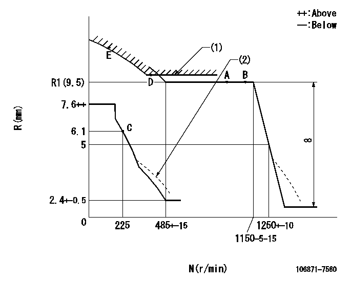
N:Pump speed
R:Rack position (mm)
(1)Excess fuel setting for starting: SXL
(2)Damper spring setting: DL
----------
SXL=10.4+-0.1mm DL=4.3-0.2mm
----------
----------
SXL=10.4+-0.1mm DL=4.3-0.2mm
----------
Timer adjustment

(1)Adjusting range
(2)Step response time
(N): Speed of the pump
(L): Load
(theta) Advance angle
(Srd1) Step response time 1
(Srd2) Step response time 2
1. Adjusting conditions for the variable timer
(1)Adjust the clearance between the pickup and the protrusion to L.
----------
L=1-0.2mm N2=800r/min C2=(8.8)deg t1=2.5--sec. t2=2.5--sec.
----------
N1=750++r/min P1=0kPa(0kgf/cm2) P2=392kPa(4kgf/cm2) C1=8.8+-0.3deg R01=0/4load R02=4/4load
----------
L=1-0.2mm N2=800r/min C2=(8.8)deg t1=2.5--sec. t2=2.5--sec.
----------
N1=750++r/min P1=0kPa(0kgf/cm2) P2=392kPa(4kgf/cm2) C1=8.8+-0.3deg R01=0/4load R02=4/4load
Speed control lever angle

F:Full speed
----------
----------
a=21deg+-5deg
----------
----------
a=21deg+-5deg
0000000901

F:Full load
I:Idle
(1)Stopper bolt setting
----------
----------
a=10deg+-5deg b=26deg+-3deg
----------
----------
a=10deg+-5deg b=26deg+-3deg
Stop lever angle
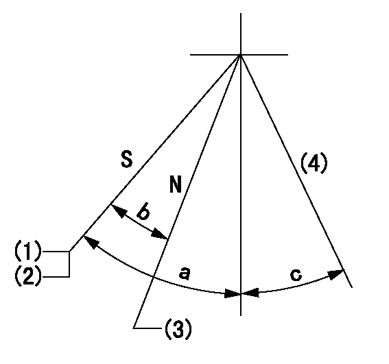
N:Pump normal
S:Stop the pump.
(1)Rack position = aa
(2)Stopper bolt setting
(3)Rack position bb
(4)Free (at shipping)
----------
aa=4-0.5mm bb=11.7mm
----------
a=43deg+7deg-5deg b=21.5deg+-5deg c=(10.5deg)
----------
aa=4-0.5mm bb=11.7mm
----------
a=43deg+7deg-5deg b=21.5deg+-5deg c=(10.5deg)
0000001501 MICRO SWITCH
Adjustment of the micro-switch
Adjust the bolt to obtain the following lever position when the micro-switch is ON.
(1)Speed N1
(2)Rack position Ra
----------
N1=325+-5r/min Ra=5.6mm
----------
----------
N1=325+-5r/min Ra=5.6mm
----------
0000001601 RACK SENSOR

V1:Supply voltage
V2f:Full side output voltage
V2i:Idle side output voltage
(A) Black
(B) Yellow
(C) Red
(D) Trimmer
(E): Shaft
(F) Nut
(G) Load lever
1. Load sensor adjustment
(1)Connect as shown in the above diagram and apply supply voltage V1.
(2)Hold the load lever (G) against the full side.
(3)Turn the shaft so that the voltage between (A) and (B) is V2.
(4)Hold the load lever (G) against the idle side.
(5)Adjust (D) so that the voltage between (A) and (B) is V2i.
(6)Repeat the above adjustments.
(7)Tighten the nut (F) at the point satisfying the standards.
(8)Hold the load lever against the full side stopper and the idle side stopper.
(9)At this time, confirm that the full side output voltage is V2f and the idle side output voltage is V2i.
----------
V1=5+-0.02V V2f=0.15+0.03V V2i=2.35-0.03V
----------
----------
V1=5+-0.02V V2f=0.15+0.03V V2i=2.35-0.03V
----------
Timing setting

(1)Pump vertical direction
(2)Coupling's key groove position at No 1 cylinder's beginning of injection
(3)-
(4)-
----------
----------
a=(40deg)
----------
----------
a=(40deg)
Information:
start by:a) remove turbocharger 1. Put the turbocharger in position on tool (A). Move tool (A) so the compressor housing is up. 2. For installation alignment purposes, make a mark on the center housing and turbine housing. Bend down the lock plates and remove six bolts (1). If some of the bolts are hard to remove, put penetrating oil on the bolt and hit the flat of the bolt head with a punch and hammer. 3. Lift the center housing and turbine wheel out of the turbine housing. If the assembly is hard to get apart, lift up on the compressor housing and hit the turbine housing with a soft hammer. 4. Remove clamp (2) from the compressor housing. For installation alignment purposes, make a mark on the center housing and the compressor housing. 5. Lift the center housing out of the compressor housing. Put the turbine wheel in tooling (B).6. Remove nut (3) with a universal socket. Remove O-ring (4).
Do not put a side force on the shaft when the nut is removed.
7. Heat the compressor wheel in oil for no more than ten minutes. The temperature of the oil must be 350° 25°F (176° 14°C).
The bearing heating oil used to heat the compressor wheel must have a flash point above 400°F (204°C).
8. Immediately after removing the compressor wheel from the oil, put the center housing in a press and use tooling (C) and (D) to remove the compressor wheel and center housing from the shaft.
Do not let the turbine wheel hit the bottom of the press.
9. Put the turbine wheel in tooling (B) and remove ring (6) and shroud (5). 10. Remove three bolts (7) and the three lock plates from center housing (8). 11. Remove plate (9) with tool (E). Remove the O-ring from plate (9). 12. Remove spacer (10) from plate (9). Remove collar (11) and thrust bearing (15). Remove bearing (12) and put a long dye mark on the top face of the bearing. Use tool (F) to remove rings (16) and (13). Remove bearing (17) and put a short dye mark on the top face of the bearing. Remove ring (14) with tool (F). The dye marks are for identification when installing the bearings.13. Inspect all parts and install new parts if needed. Use Special Instruction Form No. GMG00153-01, Turbocharger Reconditioning, Form No. FEG45138, Analyzing Turbocharger Failure and Video Tape JEG08054 (1/2 inch reel) (JEG09052-cassette), Turbocharger Reconditioning I (AIRESEARCH) for references.Assemble Turbocharger
1. Make sure all oil passages are open and clean. Put clean engine oil on all parts before assembly. 2. Install ring (3) with tool (A). Install bearing (4) with the short dye mark up. Install rings (2) and (1) with tool (A). Rings (1), (2) and (3) must be installed with the round edge toward the bearing. 3. Install shroud (5) on the turbine shaft. Install ring (6). Put 6V2055 High Vacuum Grease on ring (6) and fill the groove for the ring to one half depth all