Information injection-pump assembly
ZEXEL
106871-7480
1068717480
Rating:
Cross reference number
ZEXEL
106871-7480
1068717480
Zexel num
Bosch num
Firm num
Name
Calibration Data:
Adjustment conditions
Test oil
1404 Test oil ISO4113 or {SAEJ967d}
1404 Test oil ISO4113 or {SAEJ967d}
Test oil temperature
degC
40
40
45
Nozzle and nozzle holder
105780-8140
Bosch type code
EF8511/9A
Nozzle
105780-0000
Bosch type code
DN12SD12T
Nozzle holder
105780-2080
Bosch type code
EF8511/9
Opening pressure
MPa
17.2
Opening pressure
kgf/cm2
175
Injection pipe
Outer diameter - inner diameter - length (mm) mm 8-3-600
Outer diameter - inner diameter - length (mm) mm 8-3-600
Overflow valve
131424-4620
Overflow valve opening pressure
kPa
255
221
289
Overflow valve opening pressure
kgf/cm2
2.6
2.25
2.95
Tester oil delivery pressure
kPa
157
157
157
Tester oil delivery pressure
kgf/cm2
1.6
1.6
1.6
Direction of rotation (viewed from drive side)
Right R
Right R
Injection timing adjustment
Direction of rotation (viewed from drive side)
Right R
Right R
Injection order
1-2-7-3-
4-5-6-8
Pre-stroke
mm
4.8
4.75
4.85
Beginning of injection position
Governor side NO.1
Governor side NO.1
Difference between angles 1
Cyl.1-2 deg. 45 44.5 45.5
Cyl.1-2 deg. 45 44.5 45.5
Difference between angles 2
Cal 1-7 deg. 90 89.5 90.5
Cal 1-7 deg. 90 89.5 90.5
Difference between angles 3
Cal 1-3 deg. 135 134.5 135.5
Cal 1-3 deg. 135 134.5 135.5
Difference between angles 4
Cal 1-4 deg. 180 179.5 180.5
Cal 1-4 deg. 180 179.5 180.5
Difference between angles 5
Cal 1-5 deg. 225 224.5 225.5
Cal 1-5 deg. 225 224.5 225.5
Difference between angles 6
Cal 1-6 deg. 270 269.5 270.5
Cal 1-6 deg. 270 269.5 270.5
Difference between angles 7
Cal 1-8 deg. 315 314.5 315.5
Cal 1-8 deg. 315 314.5 315.5
Injection quantity adjustment
Adjusting point
-
Rack position
11.4
Pump speed
r/min
700
700
700
Each cylinder's injection qty
mm3/st.
156
151
161
Basic
*
Fixing the rack
*
Standard for adjustment of the maximum variation between cylinders
*
Injection quantity adjustment_02
Adjusting point
C
Rack position
6.1+-0.5
Pump speed
r/min
225
225
225
Each cylinder's injection qty
mm3/st.
20
17
23
Fixing the rack
*
Standard for adjustment of the maximum variation between cylinders
*
Injection quantity adjustment_03
Adjusting point
A
Rack position
R1(11.4)
Pump speed
r/min
700
700
700
Average injection quantity
mm3/st.
156
155
157
Basic
*
Fixing the lever
*
Boost pressure
kPa
33.3
33.3
Boost pressure
mmHg
250
250
Injection quantity adjustment_04
Adjusting point
B
Rack position
R1(11.4)
Pump speed
r/min
1100
1100
1100
Average injection quantity
mm3/st.
164
157
171
Difference in delivery
mm3/st.
14
14
14
Fixing the lever
*
Boost pressure
kPa
33.3
33.3
Boost pressure
mmHg
250
250
Injection quantity adjustment_05
Adjusting point
D
Rack position
-
Pump speed
r/min
100
100
100
Average injection quantity
mm3/st.
130
90
170
Fixing the lever
*
Boost pressure
kPa
0
0
0
Boost pressure
mmHg
0
0
0
Boost compensator adjustment
Pump speed
r/min
650
650
650
Rack position
9.9
Boost pressure
kPa
8
8
8
Boost pressure
mmHg
60
60
60
Boost compensator adjustment_02
Pump speed
r/min
650
650
650
Rack position
10.8
Boost pressure
kPa
12
10.7
13.3
Boost pressure
mmHg
90
80
100
Boost compensator adjustment_03
Pump speed
r/min
650
650
650
Rack position
R1(11.4)
Boost pressure
kPa
20
13.3
26.7
Boost pressure
mmHg
150
100
200
Timer adjustment
Pump speed
r/min
950--
Advance angle
deg.
0
0
0
Load
3/4
Remarks
Start
Start
Timer adjustment_02
Pump speed
r/min
900
Advance angle
deg.
0.5
Load
3/4
Timer adjustment_03
Pump speed
r/min
1130
Advance angle
deg.
3.5
3
4
Load
4/4
Remarks
Finish
Finish
Test data Ex:
Governor adjustment
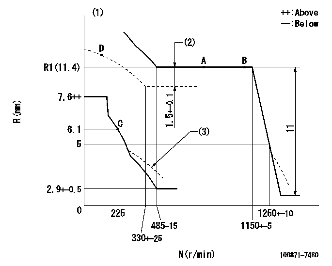
N:Pump speed
R:Rack position (mm)
(1)Boost compensator cancel stroke: BSL
(2)Boost compensator stroke
(3)Damper spring setting: DL
----------
BSL=1.6mm DL=4.3-0.2mm
----------
----------
BSL=1.6mm DL=4.3-0.2mm
----------
Speed control lever angle

F:Full speed
----------
----------
a=18deg+-5deg
----------
----------
a=18deg+-5deg
0000000901

F:Full load
I:Idle
(1)Stopper bolt setting
----------
----------
a=10deg+-5deg b=31.5deg+-3deg
----------
----------
a=10deg+-5deg b=31.5deg+-3deg
Stop lever angle
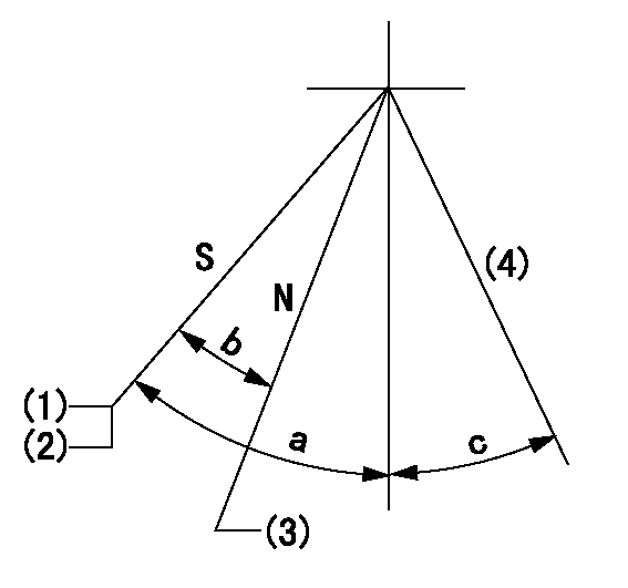
N:Engine manufacturer's normal use
S:Stop the pump.
(1)Rack position = aa
(2)Stopper bolt setting
(3)Rack position bb
(4)Free (at shipping)
----------
aa=4-0.5mm bb=14.6mm
----------
a=43deg+7deg-5deg b=30deg+-5deg c=(10.5deg)
----------
aa=4-0.5mm bb=14.6mm
----------
a=43deg+7deg-5deg b=30deg+-5deg c=(10.5deg)
0000001501 MICRO SWITCH
Adjustment of the micro-switch
Adjust the bolt to obtain the following lever position when the micro-switch is ON.
(1)Speed N1
(2)Rack position Ra
----------
N1=325+-5r/min Ra=5.6mm
----------
----------
N1=325+-5r/min Ra=5.6mm
----------
Timing setting

(1)Pump vertical direction
(2)Coupling's key groove position at No 1 cylinder's beginning of injection
(3)-
(4)-
----------
----------
a=(40deg)
----------
----------
a=(40deg)
Information:
1. Remove shaft (2). Remove pin (1) from the shaft.2. Remove pins (3) from the flyweights. Remove flyweights (4). 3. Remove ring, races (6) and the bearing from riser (follower) (5). 4. Remove cover (7) and spring (8) from the governor housing. There is force on the cover from the spring.5. Remove seal (9) from the cover. 6. Remove cover (10) for the low and high idle adjustments.7. Remove locknut and screw (13) for the high idle adjustment.8. Remove bolt (15) and the washers for the low idle adjustment.9. Remove spring (16) and the guide.10. Remove pin (14) and plate (11).11. Remove shaft (12) from the housing. 12. Remove two spacers (17) and pin (18) from the shaft. 13. Remove shaft (19) from the governor housing.14. Remove washer (20) and levers (21) and (22) from the governor housing. 15. Remove seal (23) and the bearing.16. Remove seals (24) and (25) from the governor housing.Assemble Governor
1. Install the bearing and seal in the housing with tool (A). The lip of the seal must be toward the bearing. 2. Install seal (1) in housing with tool (A). The lip of the seal must be toward inside of housing.3. Install seal (2) in the housing with tool (B). The lip of the seal must be toward the inside of the housing. 4. Install shaft (3) in the housing. 5. Install plates (4), spacers (8) and pin (7) on shaft (5).6. Install shaft (5) in the housing and through washer (9) and levers (6). 7. Install pin (11) in the holes of the plates.8. Install screw (10) and the locknut for the high idle adjustment.9. Install spring (13) and the guide.10. Install bolt (12) and the washer for the low idle adjustment.11. Push plate and pin (11) over toward bolt (12) and tighten the bolt. 12. Install the seal in cover (14) with tooling (B). The lip of the seal must be toward the inside. 13. Install spring (15) in the cover. Install cover (14) on the housing.
Spring (15) must be installed with the end of the spring in the position shown.
14. Install the cover (16) for the idle adjustment screws. 15. Install bearing (19) between races (18) on riser (follower) (17). Install ring (20). Ring (20) holds the washers on the riser (follower).16. Install the pin in shaft (23). 17. Install flyweights (22) and pin (21).18. Install shaft (23) in the flyweight assembly.end by: a) connection of governor to fuel injection pump housingb) Make adjustment of fuel system setting (See Fuel System Setting in Testing and Adjusting.)