Information injection-pump assembly
ZEXEL
106871-7420
1068717420
Rating:
Cross reference number
ZEXEL
106871-7420
1068717420
Zexel num
Bosch num
Firm num
Name
Calibration Data:
Adjustment conditions
Test oil
1404 Test oil ISO4113 or {SAEJ967d}
1404 Test oil ISO4113 or {SAEJ967d}
Test oil temperature
degC
40
40
45
Nozzle and nozzle holder
105780-8140
Bosch type code
EF8511/9A
Nozzle
105780-0000
Bosch type code
DN12SD12T
Nozzle holder
105780-2080
Bosch type code
EF8511/9
Opening pressure
MPa
17.2
Opening pressure
kgf/cm2
175
Injection pipe
Outer diameter - inner diameter - length (mm) mm 8-3-600
Outer diameter - inner diameter - length (mm) mm 8-3-600
Overflow valve
131424-4620
Overflow valve opening pressure
kPa
255
221
289
Overflow valve opening pressure
kgf/cm2
2.6
2.25
2.95
Tester oil delivery pressure
kPa
157
157
157
Tester oil delivery pressure
kgf/cm2
1.6
1.6
1.6
Direction of rotation (viewed from drive side)
Right R
Right R
Injection timing adjustment
Direction of rotation (viewed from drive side)
Right R
Right R
Injection order
1-2-7-3-
4-5-6-8
Pre-stroke
mm
4.8
4.75
4.85
Beginning of injection position
Governor side NO.1
Governor side NO.1
Difference between angles 1
Cyl.1-2 deg. 45 44.5 45.5
Cyl.1-2 deg. 45 44.5 45.5
Difference between angles 2
Cal 1-7 deg. 90 89.5 90.5
Cal 1-7 deg. 90 89.5 90.5
Difference between angles 3
Cal 1-3 deg. 135 134.5 135.5
Cal 1-3 deg. 135 134.5 135.5
Difference between angles 4
Cal 1-4 deg. 180 179.5 180.5
Cal 1-4 deg. 180 179.5 180.5
Difference between angles 5
Cal 1-5 deg. 225 224.5 225.5
Cal 1-5 deg. 225 224.5 225.5
Difference between angles 6
Cal 1-6 deg. 270 269.5 270.5
Cal 1-6 deg. 270 269.5 270.5
Difference between angles 7
Cal 1-8 deg. 315 314.5 315.5
Cal 1-8 deg. 315 314.5 315.5
Injection quantity adjustment
Adjusting point
-
Rack position
10.7+-0.
5
Pump speed
r/min
700
700
700
Each cylinder's injection qty
mm3/st.
137
132.9
141.1
Basic
*
Fixing the rack
*
Standard for adjustment of the maximum variation between cylinders
*
Injection quantity adjustment_02
Adjusting point
C
Rack position
R2(6)
Pump speed
r/min
225
225
225
Each cylinder's injection qty
mm3/st.
18.5
16
21
Fixing the rack
*
Standard for adjustment of the maximum variation between cylinders
*
Injection quantity adjustment_03
Adjusting point
A
Rack position
R1(10.7)
Pump speed
r/min
700
700
700
Average injection quantity
mm3/st.
137
136
138
Basic
*
Fixing the lever
*
Boost pressure
kPa
33.3
33.3
Boost pressure
mmHg
250
250
Injection quantity adjustment_04
Adjusting point
B
Rack position
R1+0.2
Pump speed
r/min
1100
1100
1100
Average injection quantity
mm3/st.
149.5
145.5
153.5
Fixing the lever
*
Boost pressure
kPa
33.3
33.3
Boost pressure
mmHg
250
250
Injection quantity adjustment_05
Adjusting point
D
Rack position
-
Pump speed
r/min
200
200
200
Average injection quantity
mm3/st.
120
80
160
Fixing the lever
*
Boost pressure
kPa
0
0
0
Boost pressure
mmHg
0
0
0
Boost compensator adjustment
Pump speed
r/min
400
400
400
Rack position
(9.3)
Boost pressure
kPa
2
2
2
Boost pressure
mmHg
15
15
15
Boost compensator adjustment_02
Pump speed
r/min
400
400
400
Rack position
R1(10.7)
Boost pressure
kPa
12.7
11.4
14
Boost pressure
mmHg
95
85
105
Boost compensator adjustment_03
Pump speed
r/min
400
400
400
Rack position
(11.9)
Boost pressure
kPa
20
20
20
Boost pressure
mmHg
150
150
150
Timer adjustment
Pump speed
r/min
950--
Advance angle
deg.
0
0
0
Remarks
Start
Start
Timer adjustment_02
Pump speed
r/min
1100
Advance angle
deg.
4
3.5
4.5
Remarks
Finish
Finish
Test data Ex:
Governor adjustment
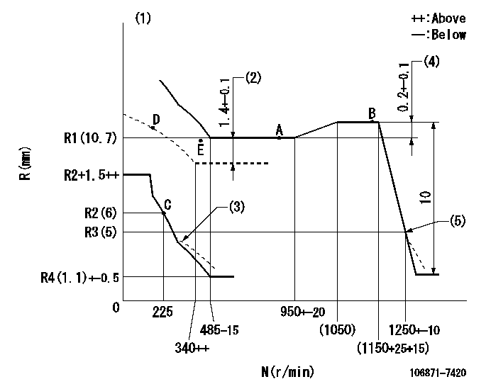
N:Pump speed
R:Rack position (mm)
(1)Boost compensator cancel stroke: BSL
(2)Boost compensator stroke
(3)Damper spring setting: DL
(4)Rack difference between N = N1 and N = N2
(5)Injection quantity Q = Q1
----------
BSL=1.6mm DL=R3(5)-0.2mm N1=1100r/min N2=700r/min Q1=21.5+-2.5mm3/st
----------
----------
BSL=1.6mm DL=R3(5)-0.2mm N1=1100r/min N2=700r/min Q1=21.5+-2.5mm3/st
----------
Speed control lever angle

F:Full speed
----------
----------
a=(18deg)+-5deg
----------
----------
a=(18deg)+-5deg
0000000901
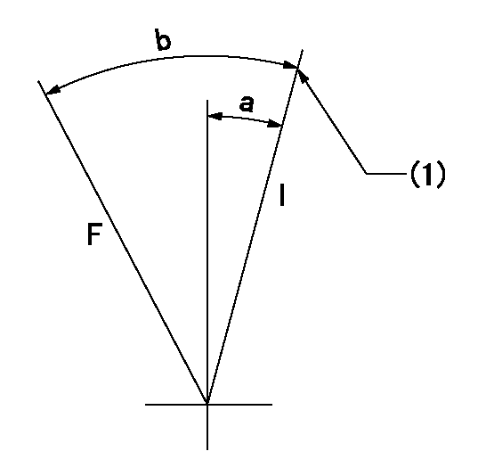
F:Full load
I:Idle
(1)Stopper bolt setting
----------
----------
a=10deg+-5deg b=(32.5deg)+-3deg
----------
----------
a=10deg+-5deg b=(32.5deg)+-3deg
Stop lever angle
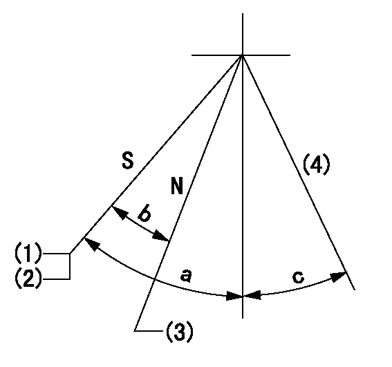
N:Engine manufacturer's normal use
S:Stop the pump.
(1)Stopper bolt setting
(2)Rack position = aa
(3)Rack position bb
(4)Free (at shipping)
----------
aa=4-0.5mm bb=14.6mm
----------
a=43deg+7deg-5deg b=30deg+-5deg c=(10.5deg)
----------
aa=4-0.5mm bb=14.6mm
----------
a=43deg+7deg-5deg b=30deg+-5deg c=(10.5deg)
0000001501 MICRO SWITCH
Adjustment of the micro-switch
Adjust the bolt to obtain the following lever position when the micro-switch is ON.
(1)Speed N1
(2)Rack position Ra
----------
N1=325+-5r/min Ra=R2(6)-0.3mm
----------
----------
N1=325+-5r/min Ra=R2(6)-0.3mm
----------
Timing setting

(1)Pump vertical direction
(2)Coupling's key groove position at No 1 cylinder's beginning of injection
(3)-
(4)-
----------
----------
a=(40deg)
----------
----------
a=(40deg)
Information:
Recommended Procedure1. Air in Fuel System ... With air in the fuel system, the engine will normally be difficult to start, run rough, and release a large amount of white smoke. If the engine will not start, loosen a fuel injection line nut at the cylinder head. With the governor lever in the shutoff position, operate the fuel priming pump until the flow of fuel from the loosened fuel injection line is free of air. Tighten the fuel line nut. Fasten the priming pump and start the engine. If the engine still does not run smooth or releases a large amount of white smoke, loosen the fuel line nuts one at a time at the cylinder head until the fuel that comes out is free of air. Tighten the fuel line nuts. If the air can not be removed in this way, put 5 psi (35 kPa) of air pressure to the fuel tank.
Do not use more than 8 psi (55 kPa) of air pressure in the fuel tank or damage to the tank may result.
Check for leaks at the connections between the fuel tank and the fuel transfer pump. If leaks are found, tighten the connections or replace the lines. If there are no visual leaks, remove the fuel supply line from the tank and connect it to an outside fuel supply. If this corrects the problem, the suction line (standpipe) inside the fuel tank has a leak.2. Valve Adjustment Not Correct ... Check and make necessary adjustments as per Testing and Adjusting section of this Service Manual. Intake valve clearance is .015 in. (0.38 mm) and exhaust valve clearance is .025 in. (0.64 mm). Also check for a bent or broken push rod.3. Fuel Injection Timing Not Correct ... Check and make necessary adjustments as per Testing and Adjusting section of this Service Manual.4. Automatic Timing Advance Does Not Operate Correctly ... Check with engine warm. Use the 1P3500 Timing Light Group. Special Instruction Form No. SMHS6964 gives the test procedure. If the timing light is not available, make rapid "acceleration" (increase in speed) from low idle to high idle. Engine must have smooth acceleration. A timing advance that does not operate correctly can cause delays of the engine acceleration at some rpm before high idle, or possibly cause the engine to run rough and have exhaust noise (backfire) during acceleration. This condition is difficult to find if engine acceleration is slow or at a constant engine rpm.5. Bad Fuel Nozzle(s) ... Find a bad nozzle by running engine at the rpm where it runs rough. Loosen the fuel line nut at the cylinder head enough to stop fuel supply to that cylinder. Each cylinder must be checked this way. If a cylinder is found where loosening of the nut makes no difference in the rough running, test the nozzle for that cylinder. To test a nozzle, remove the nozzle from the engine and test as per Testing and Adjusting section of this Service Manual.6.