Information injection-pump assembly
BOSCH
9 400 611 546
9400611546
ZEXEL
106871-5670
1068715670
NISSAN-DIESEL
1671397875
1671397875
Rating:
Service parts 106871-5670 INJECTION-PUMP ASSEMBLY:
1.
_
7.
COUPLING PLATE
8.
_
9.
_
11.
Nozzle and Holder
16600-97079
12.
Open Pre:MPa(Kqf/cm2)
17.7{180}/22.6{230}
14.
NOZZLE
Include in #1:
106871-5670
as INJECTION-PUMP ASSEMBLY
Cross reference number
BOSCH
9 400 611 546
9400611546
ZEXEL
106871-5670
1068715670
NISSAN-DIESEL
1671397875
1671397875
Zexel num
Bosch num
Firm num
Name
106871-5670
9 400 611 546
1671397875 NISSAN-DIESEL
INJECTION-PUMP ASSEMBLY
RF8TD K 14CD INJECTION PUMP ASSY PE8P PE
RF8TD K 14CD INJECTION PUMP ASSY PE8P PE
Calibration Data:
Adjustment conditions
Test oil
1404 Test oil ISO4113 or {SAEJ967d}
1404 Test oil ISO4113 or {SAEJ967d}
Test oil temperature
degC
40
40
45
Nozzle and nozzle holder
105780-8140
Bosch type code
EF8511/9A
Nozzle
105780-0000
Bosch type code
DN12SD12T
Nozzle holder
105780-2080
Bosch type code
EF8511/9
Opening pressure
MPa
17.2
Opening pressure
kgf/cm2
175
Injection pipe
Outer diameter - inner diameter - length (mm) mm 8-3-600
Outer diameter - inner diameter - length (mm) mm 8-3-600
Overflow valve
132424-0620
Overflow valve opening pressure
kPa
157
123
191
Overflow valve opening pressure
kgf/cm2
1.6
1.25
1.95
Tester oil delivery pressure
kPa
157
157
157
Tester oil delivery pressure
kgf/cm2
1.6
1.6
1.6
Direction of rotation (viewed from drive side)
Right R
Right R
Injection timing adjustment
Direction of rotation (viewed from drive side)
Right R
Right R
Injection order
1-8-7-5-
4-3-6-2
Pre-stroke
mm
3.9
3.85
3.95
Beginning of injection position
Governor side NO.1
Governor side NO.1
Difference between angles 1
Cal 1-8 deg. 45 44.5 45.5
Cal 1-8 deg. 45 44.5 45.5
Difference between angles 2
Cal 1-7 deg. 90 89.5 90.5
Cal 1-7 deg. 90 89.5 90.5
Difference between angles 3
Cal 1-5 deg. 135 134.5 135.5
Cal 1-5 deg. 135 134.5 135.5
Difference between angles 4
Cal 1-4 deg. 180 179.5 180.5
Cal 1-4 deg. 180 179.5 180.5
Difference between angles 5
Cal 1-3 deg. 225 224.5 225.5
Cal 1-3 deg. 225 224.5 225.5
Difference between angles 6
Cal 1-6 deg. 270 269.5 270.5
Cal 1-6 deg. 270 269.5 270.5
Difference between angles 7
Cyl.1-2 deg. 315 314.5 315.5
Cyl.1-2 deg. 315 314.5 315.5
Injection quantity adjustment
Adjusting point
A
Rack position
11.6
Pump speed
r/min
600
600
600
Average injection quantity
mm3/st.
211
209
213
Max. variation between cylinders
%
0
-4
4
Basic
*
Fixing the lever
*
Boost pressure
kPa
33.3
33.3
Boost pressure
mmHg
250
250
Injection quantity adjustment_02
Adjusting point
C
Rack position
5.3+-0.5
Pump speed
r/min
235
235
235
Average injection quantity
mm3/st.
11.5
9.5
13.5
Max. variation between cylinders
%
0
-10
10
Fixing the rack
*
Boost pressure
kPa
0
0
0
Boost pressure
mmHg
0
0
0
Injection quantity adjustment_03
Adjusting point
E
Rack position
12.1+-0.
1
Pump speed
r/min
100
100
100
Average injection quantity
mm3/st.
150
150
Fixing the lever
*
Boost pressure
kPa
33.3
33.3
Boost pressure
mmHg
250
250
Rack limit
*
Boost compensator adjustment
Pump speed
r/min
400
400
400
Rack position
R1(8.8)
Boost pressure
kPa
5.3
5.3
5.3
Boost pressure
mmHg
40
40
40
Boost compensator adjustment_02
Pump speed
r/min
400
400
400
Rack position
11.2
Boost pressure
kPa
12
10.7
13.3
Boost pressure
mmHg
90
80
100
Boost compensator adjustment_03
Pump speed
r/min
400
400
400
Rack position
12.1+-0.
1
Boost pressure
kPa
20
20
20
Boost pressure
mmHg
150
150
150
Timer adjustment
Pump speed
r/min
770--
Advance angle
deg.
0
0
0
Remarks
Start
Start
Timer adjustment_02
Pump speed
r/min
720
Advance angle
deg.
0.3
Timer adjustment_03
Pump speed
r/min
930
Advance angle
deg.
3
2.7
3.3
Remarks
Finish
Finish
Test data Ex:
Governor adjustment
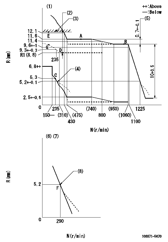
N:Pump speed
R:Rack position (mm)
(1)Tolerance for racks not indicated: +-0.05mm.
(2)Boost compensator stroke: BCL
(3)Rack limit using stop lever: RA
(4)Damper spring setting: DL
(5)Rack difference between N = N1 and N = N2
(6)Variable speed specification: idling adjustment
(7)Fix the lever at the full-load position at delivery.
(8)Main spring setting
----------
BCL=(3.3)mm RA=12.1+-0.1mm DL=4.8-0.2mm N1=1000r/min N2=600r/min
----------
----------
BCL=(3.3)mm RA=12.1+-0.1mm DL=4.8-0.2mm N1=1000r/min N2=600r/min
----------
Speed control lever angle

F:Full speed
I:Idle
(1)Pump speed = aa
(2)Set the stopper bolt (fixed at full-load position at delivery.)
----------
aa=290r/min
----------
a=14deg+-5deg b=4deg+-5deg
----------
aa=290r/min
----------
a=14deg+-5deg b=4deg+-5deg
0000000901

F:Full load
I:Idle
(1)Stopper bolt setting
(2)Use the hole at R = aa
----------
aa=64.3mm
----------
a=18.5deg+-5deg b=33.5deg+-3deg
----------
aa=64.3mm
----------
a=18.5deg+-5deg b=33.5deg+-3deg
Stop lever angle
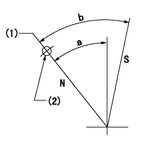
N:Pump normal
S:Stop the pump.
(1)Rack position = aa
(2)Use the pin at R = bb
----------
aa=12.1+-0.1mm bb=46mm
----------
a=36.5deg+-5deg b=38.5deg+-5deg
----------
aa=12.1+-0.1mm bb=46mm
----------
a=36.5deg+-5deg b=38.5deg+-5deg
Timing setting

(1)Pump vertical direction
(2)Position of the coupling's key groove at the beginning of injection of the No. 8 cylinder.
(3)-
(4)-
----------
----------
a=(90deg)
----------
----------
a=(90deg)
Information:
(1) Torque for three studs to hold the water pump ... 27 4 N m (20 3 lb.ft.)(2) Plug (two on front and two on rear). Put 5P3413 Pipe Sealant on the threads of the plugs.(3) Length of dowels (four) out of the block face ... 18.5 0.5 mm (.73 .02 in.)(4) Thickness of the gasket between the cylinder block and top plates ... 0.21 0.03 mm (.008 .001 in.)(5) Thickness of the top plates ... 8.59 0.03 mm (.338 .001 in.)(6) Make reference to Cylinder Liner Projection, for the height of the liner.(7) Bore in the block for the camshaft bearings (seven bores) ... 76.835 0.018 mm (3.0250 .0007 in.)(8) Torque for one plug on front and two on rear of the block ... 80 14 N m (60 10 lb.ft.)Put 5P3413 Pipe Sealant on the threads of the plug.(9) Bore in the block for the main bearings (with main bearing caps torqued):Standard, original size (new) ... 129.891 0.013 mm (5.1138 .0005 in.)0.64 mm (.025 in.) larger than original size ... 130.526 0.013 mm (5.1388 .0005 in.)(10) Projection of dowels (four) out of the front and rear faces of the block ... 19.0 0.5 mm (.75 .02 in.)(11) Width of slot for bearing cap ... 215.900 0.013 mm (8.5000 .0005 in.)Width of bearing cap ... 215.900 0.013 mm (8.5000 .0005 in.)Clearance between slot and bearing cap (with main bearing caps torqued) 0.025 mm (.0010 in.) tight to 0.025 mm (.0010 in.) loose(12) Torque for the bolts that hold the piston cooling tubes ... 24 7 N m (18 5 lb.ft.)(13) Torque for the bolts that hold the caps for the main bearings:Install the main bearing caps with the marks (arrow) toward the front of the engine. Each cap has a number on the bottom and must be installed in the same position as the correct number on the left side of the block pan rail.a. Put 2P2506 Thread Lubricant on the threads of the bolts.b. Tighten the bolts on left (tab) side to ... 260 14 N m (190 10 lb.ft.)c. Tighten the bolts on right side to ... 260 14 N m (190 10 lb.ft.)d. Put a mark on each bolt and cap.e. Tighten the bolts on right side, from the mark ... 120°f. Tighten the bolts on left side, from the mark ... 120° (14) Dimension (new) from the centerline of crankshaft bearing bore to top of block (top deck) ... 419.10 0.15 mm (16.00 .006 in.)(15) Dimension (new) from centerline of crankshaft bearing bore to bottom of block (pan rails) ... 165.10 0.10 mm (6.500 .004 in.)
Right Side Of Engine(16) Plug. Two plugs - one located at front and the other located at rear of right cylinder bank.(17) Plug. Use 6V1541 Quick Cure Primer and 9S3265 Retaining Compound in the plug bores
Right Side Of Engine(16) Plug. Two plugs - one located at front and the other located at rear of right cylinder bank.(17) Plug. Use 6V1541 Quick Cure Primer and 9S3265 Retaining Compound in the plug bores
Have questions with 106871-5670?
Group cross 106871-5670 ZEXEL
Nissan-Diesel
Nissan-Diesel
Nissan-Diesel
Nissan-Diesel
Nissan-Diesel
Nissan-Diesel
Nissan-Diesel
106871-5670
9 400 611 546
1671397875
INJECTION-PUMP ASSEMBLY
RF8TD
RF8TD