Information injection-pump assembly
BOSCH
F 01G 09U 0AE
f01g09u0ae
ZEXEL
106871-5662
1068715662

Rating:
Cross reference number
BOSCH
F 01G 09U 0AE
f01g09u0ae
ZEXEL
106871-5662
1068715662
Zexel num
Bosch num
Firm num
Name
Calibration Data:
Adjustment conditions
Test oil
1404 Test oil ISO4113 or {SAEJ967d}
1404 Test oil ISO4113 or {SAEJ967d}
Test oil temperature
degC
40
40
45
Nozzle and nozzle holder
105780-8250
Bosch type code
1 688 901 101
Nozzle
105780-0120
Bosch type code
1 688 901 990
Nozzle holder
105780-2190
Opening pressure
MPa
20.7
Opening pressure
kgf/cm2
211
Injection pipe
Outer diameter - inner diameter - length (mm) mm 8-3-600
Outer diameter - inner diameter - length (mm) mm 8-3-600
Overflow valve
131425-0120
Overflow valve opening pressure
kPa
157
123
191
Overflow valve opening pressure
kgf/cm2
1.6
1.25
1.95
Tester oil delivery pressure
kPa
255
255
255
Tester oil delivery pressure
kgf/cm2
2.6
2.6
2.6
RED3 control unit part number
407910-3
960
RED3 rack sensor specifications
mm
19
Direction of rotation (viewed from drive side)
Right R
Right R
Injection timing adjustment
Direction of rotation (viewed from drive side)
Right R
Right R
Injection order
1-8-7-5-
4-3-6-2
Pre-stroke
mm
3.9
3.87
3.93
Beginning of injection position
Governor side NO.1
Governor side NO.1
Difference between angles 1
Cal 1-8 deg. 45 44.75 45.25
Cal 1-8 deg. 45 44.75 45.25
Difference between angles 2
Cal 1-7 deg. 90 89.75 90.25
Cal 1-7 deg. 90 89.75 90.25
Difference between angles 3
Cal 1-5 deg. 135 134.75 135.25
Cal 1-5 deg. 135 134.75 135.25
Difference between angles 4
Cal 1-4 deg. 180 179.75 180.25
Cal 1-4 deg. 180 179.75 180.25
Difference between angles 5
Cal 1-3 deg. 225 224.75 225.25
Cal 1-3 deg. 225 224.75 225.25
Difference between angles 6
Cal 1-6 deg. 270 269.75 270.25
Cal 1-6 deg. 270 269.75 270.25
Difference between angles 7
Cyl.1-2 deg. 315 314.75 315.25
Cyl.1-2 deg. 315 314.75 315.25
Injection quantity adjustment
Rack position
(13.7)
Vist
V
1.8
1.8
1.8
Pump speed
r/min
600
600
600
Average injection quantity
mm3/st.
141.5
139.5
143.5
Max. variation between cylinders
%
0
-4
4
Basic
*
Injection quantity adjustment_02
Rack position
(9)
Vist
V
2.5
2.4
2.6
Pump speed
r/min
330
330
330
Average injection quantity
mm3/st.
16
14
18
Max. variation between cylinders
%
0
-10
10
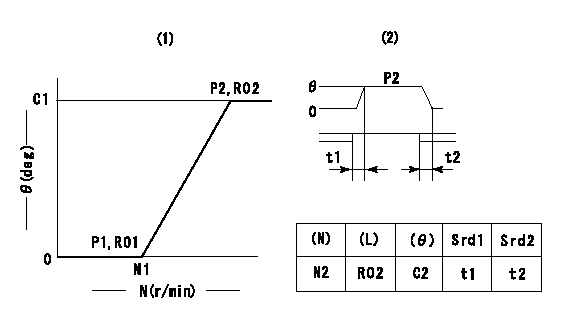
Test data Ex:
Governor adjustment

(1)Adjusting range
(2)Step response time
(N): Speed of the pump
(L): Load
(theta) Advance angle
(Srd1) Step response time 1
(Srd2) Step response time 2
1. Adjusting conditions for the variable timer
(1)Adjust the clearance between the pickup and the protrusion to L.
----------
L=1-0.2mm N2=800r/min C2=(9)deg t1=1.7--sec. t2=1.7--sec.
----------
N1=1000++r/min P1=0kPa(0kgf/cm2) P2=392kPa(4kgf/cm2) C1=9+-0.3deg R01=0/4load R02=4/4load
----------
L=1-0.2mm N2=800r/min C2=(9)deg t1=1.7--sec. t2=1.7--sec.
----------
N1=1000++r/min P1=0kPa(0kgf/cm2) P2=392kPa(4kgf/cm2) C1=9+-0.3deg R01=0/4load R02=4/4load
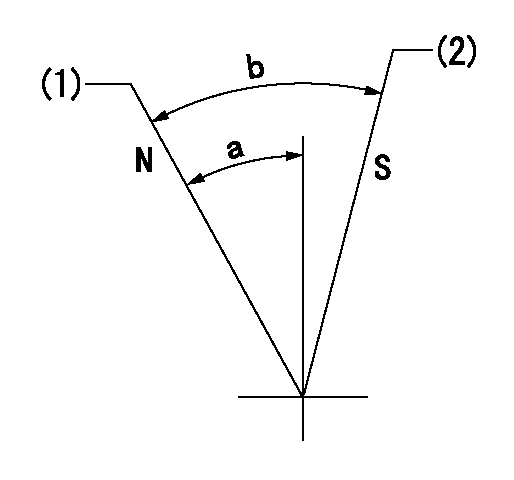
Speed control lever angle

N:Pump normal
S:Stop the pump.
(1)Rack position = aa
(2)Rack position bb
----------
aa=20mm bb=1mm
----------
a=27deg+-5deg b=37deg+-5deg
----------
aa=20mm bb=1mm
----------
a=27deg+-5deg b=37deg+-5deg
0000000901

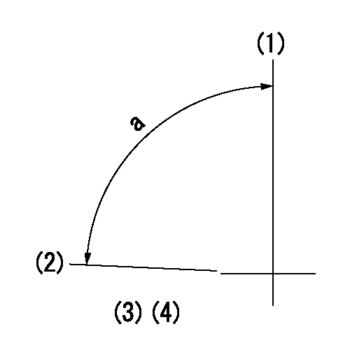
(1)Pump vertical direction
(2)Position of the coupling's key groove at the beginning of injection of the No. 8 cylinder.
(3)-
(4)-
----------
----------
a=(90deg)
----------
----------
a=(90deg)
Stop lever angle

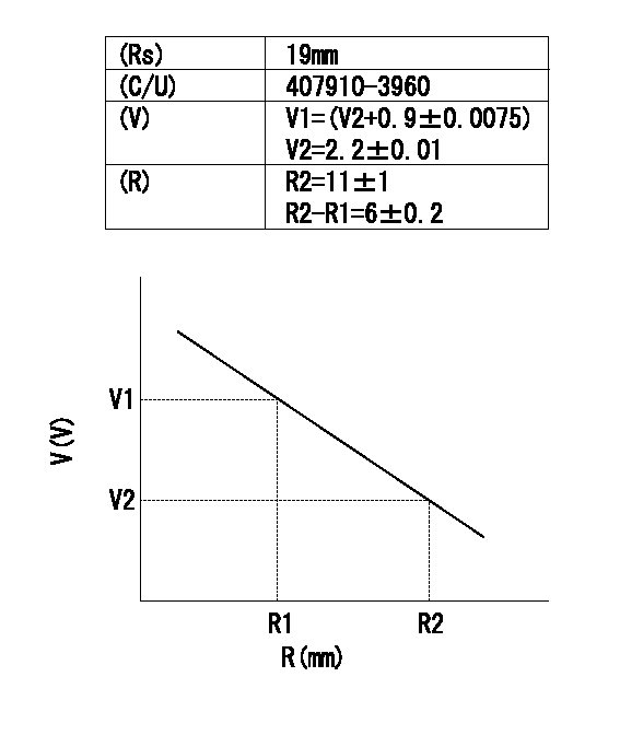
(Rs) rack sensor specifications
(C/U) control unit part number
(V) Rack sensor output voltage
(R) Rack position (mm)
1. Confirming governor output characteristics (rack 19 mm, span 6 mm)
(1)When the output voltages of the rack sensor are V1 and V2, check that the rack positions R1 and R2 in the table above are satisfied.
----------
----------
----------
----------
Information:
(1) End play for shaft (new) ... 0.114 0.038 mm (.0045 .0015 in.) Maximum permissible end play (worn) ... 0.20 mm (.008 in.)(2) Tighten band clamps with procedure that follows: a. Tighten to ... 13.6 1.1 N (120 10 lb.in.)b. Tap (hit) clamp lightly all around.c. Tighten again to ... 13.6 1.1 N (120 10 lb.in.)(3) Thickness of thrust bearing ... 5.36 0.03 mm (.211 .001 in.)(4) Diameter of shaft (new) ... 14.254 to 14.262 mm (.5612 to .5615 in.) Bore in the bearing (new) ... 14.293 to 14.300 mm (.5627 to .5630 in.)Maximum permissible clearance between bearing and shaft (worn) ... 0.08 mm (.003 in.)(5) Maximum permissible gap of oil seal ring, measured in bore of housing ... 0.23 mm (.009 in.)(6) Bore in housing (new) ... 22.255 to 22.268 mm (.8762 to .8767 in.) Outside diameter of the bearing (new) ... 22.144 to 22.154 mm (.8718 to .8722 in.)Maximum permissible clearance between bearing and bore in housing (worn) ... 0.15 mm (.006 in.)(7) Turbocharger impeller installation at room temperature: a. Put 6V1541 Quick Cure Primer on the nut and the shaft threads to clean them, if necessary.b. Put a small amount of 9S3265 Retaining Compound on the nut and shaft threads.
Do not let the retaining compound get into the compressor wheel bore or on the shaft, because it can make removal of the compressor wheel difficult during future turbocharger disassembly.
c. Put a small amount of lubricant, such as Lubriplate, on the nut seat area on the compressor. Do not put lubricant on the threads.d. Tighten the compressor wheel retainer nut to a torque of ... 60 3 N m (44 2 lb.ft.)
Do not bend or add stress to the shaft when the nut is tightened.
(8) Thickness of each thrust ring ... 2.553 0.013 mm (.1005 .0005 in.)(9) Torque for four nuts (put 5P3931 Anti-Seize Compound on threads) ... 55 5 N m (40 4 lb.ft.)