Information injection-pump assembly
BOSCH
9 400 611 348
9400611348
ZEXEL
106871-5653
1068715653
Rating:
Service parts 106871-5653 INJECTION-PUMP ASSEMBLY:
1.
_
7.
COUPLING PLATE
8.
_
9.
_
11.
Nozzle and Holder
16600-97163
12.
Open Pre:MPa(Kqf/cm2)
17.7{180}/22.6{230}
14.
NOZZLE
Include in #1:
106871-5653
as INJECTION-PUMP ASSEMBLY
Cross reference number
BOSCH
9 400 611 348
9400611348
ZEXEL
106871-5653
1068715653
Zexel num
Bosch num
Firm num
Name
Calibration Data:
Adjustment conditions
Test oil
1404 Test oil ISO4113 or {SAEJ967d}
1404 Test oil ISO4113 or {SAEJ967d}
Test oil temperature
degC
40
40
45
Nozzle and nozzle holder
105780-8250
Bosch type code
1 688 901 101
Nozzle
105780-0120
Bosch type code
1 688 901 990
Nozzle holder
105780-2190
Opening pressure
MPa
20.7
Opening pressure
kgf/cm2
211
Injection pipe
Outer diameter - inner diameter - length (mm) mm 8-3-600
Outer diameter - inner diameter - length (mm) mm 8-3-600
Overflow valve
131425-0120
Overflow valve opening pressure
kPa
157
123
191
Overflow valve opening pressure
kgf/cm2
1.6
1.25
1.95
Tester oil delivery pressure
kPa
255
255
255
Tester oil delivery pressure
kgf/cm2
2.6
2.6
2.6
RED3 control unit part number
407910-3
960
RED3 rack sensor specifications
mm
19
Direction of rotation (viewed from drive side)
Right R
Right R
Injection timing adjustment
Direction of rotation (viewed from drive side)
Right R
Right R
Injection order
1-8-7-5-
4-3-6-2
Pre-stroke
mm
3.9
3.87
3.93
Beginning of injection position
Governor side NO.1
Governor side NO.1
Difference between angles 1
Cal 1-8 deg. 45 44.75 45.25
Cal 1-8 deg. 45 44.75 45.25
Difference between angles 2
Cal 1-7 deg. 90 89.75 90.25
Cal 1-7 deg. 90 89.75 90.25
Difference between angles 3
Cal 1-5 deg. 135 134.75 135.25
Cal 1-5 deg. 135 134.75 135.25
Difference between angles 4
Cal 1-4 deg. 180 179.75 180.25
Cal 1-4 deg. 180 179.75 180.25
Difference between angles 5
Cal 1-3 deg. 225 224.75 225.25
Cal 1-3 deg. 225 224.75 225.25
Difference between angles 6
Cal 1-6 deg. 270 269.75 270.25
Cal 1-6 deg. 270 269.75 270.25
Difference between angles 7
Cyl.1-2 deg. 315 314.75 315.25
Cyl.1-2 deg. 315 314.75 315.25
Injection quantity adjustment
Rack position
(13.7)
Vist
V
1.8
1.8
1.8
Pump speed
r/min
600
600
600
Average injection quantity
mm3/st.
141.5
139.5
143.5
Max. variation between cylinders
%
0
-4
4
Basic
*
Injection quantity adjustment_02
Rack position
(9)
Vist
V
2.5
2.4
2.6
Pump speed
r/min
330
330
330
Average injection quantity
mm3/st.
16
14
18
Max. variation between cylinders
%
0
-10
10
Test data Ex:
Governor adjustment
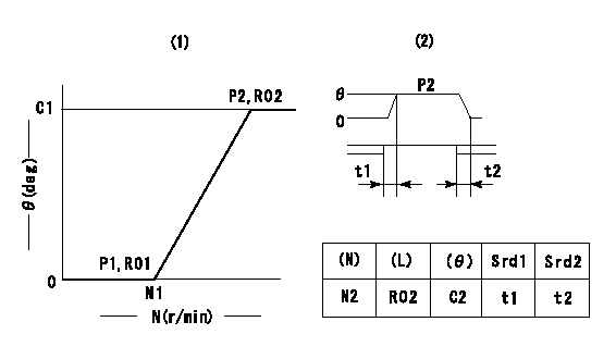
(1)Adjusting range
(2)Step response time
(N): Speed of the pump
(L): Load
(theta) Advance angle
(Srd1) Step response time 1
(Srd2) Step response time 2
1. Adjusting conditions for the variable timer
(1)Adjust the clearance between the pickup and the protrusion to L.
----------
L=1-0.2mm N2=800r/min C2=(9deg) t1=1.7--sec. t2=1.7--sec.
----------
N1=1000++r/min P1=0kPa(0kgf/cm2) P2=392kPa(4kgf/cm2) C1=9+-0.3deg R01=0/4load R02=4/4load
----------
L=1-0.2mm N2=800r/min C2=(9deg) t1=1.7--sec. t2=1.7--sec.
----------
N1=1000++r/min P1=0kPa(0kgf/cm2) P2=392kPa(4kgf/cm2) C1=9+-0.3deg R01=0/4load R02=4/4load
Speed control lever angle
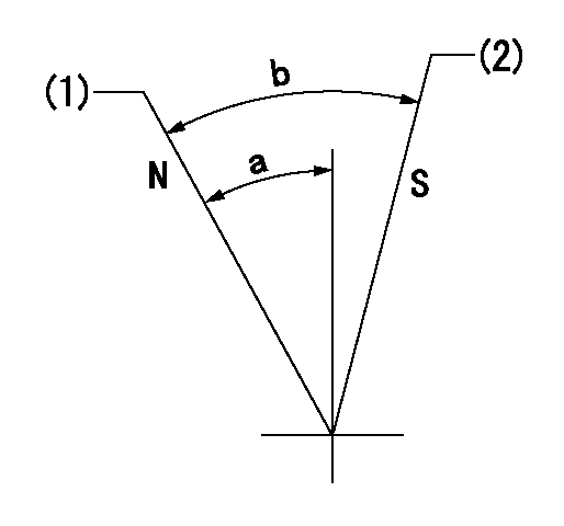
N:Pump normal
S:Stop the pump.
(1)Rack position = aa
(2)Rack position bb
----------
aa=20mm bb=1mm
----------
a=27deg+-5deg b=37deg+-5deg
----------
aa=20mm bb=1mm
----------
a=27deg+-5deg b=37deg+-5deg
0000000901
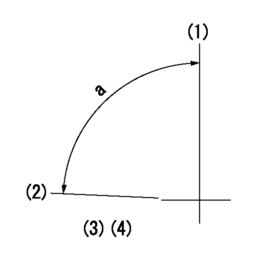
(1)Pump vertical direction
(2)Position of the coupling's key groove at the beginning of injection of the No. 8 cylinder.
(3)-
(4)-
----------
----------
a=(90deg)
----------
----------
a=(90deg)
Stop lever angle
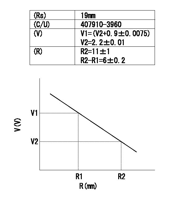
(Rs) rack sensor specifications
(C/U) control unit part number
(V) Rack sensor output voltage
(R) Rack position (mm)
1. Confirming governor output characteristics (rack 19 mm, span 6 mm)
(1)When the output voltages of the rack sensor are V1 and V2, check that the rack positions R1 and R2 in the table above are satisfied.
----------
----------
----------
----------
Information:
Later Governors Any adjustment to the governor must be made only by a person approved by Caterpillar or by a Caterpillar Dealer.(1) Torque for nut ... 12 4 N m (9 3 lb.ft.).(2) 6N8793 Spring: Length under test force ... 19.05 mm (.750 in.)Test force ... 2.00 0.13 N (.45 .03 lb.)Free length after test ... 41.9 mm (1.65 in.)Outside diameter ... 9.40 mm (.370 in.)(3) Seat. Install a spring washer, flat washer and spring washer between seat (3) and spring (4) as shown.(4) 9L6449 Spring for the governor: Color code ... one green stripe, one brown stripePut force on spring of ... 22 N (5 lb.)Then add more force to make spring shorter by ... 22.86 mm (.900 in.)Total test force ... 86.6 1.8 N (19.4 .4 lb.)Free length after test ... 56.9 1 mm (2.24 .04 in.)Outside diameter ... 35.23 mm (1.387 in.)
Install Spring Washers As Shown(4) 9L6448 Spring for the governor: Color code ... one green stripe, one yellow stripePut force on spring of ... 22.24 N (4.00 lb.)Then add more force to make spring shorter by: ... 22.86 mm (.900 in.)Total test force ... 73.00 1.50 N (16.60 .30 lb.)Free length after test ... 56.9 0.8 mm (2.24 .03 in.)Outside diameter ... 35.3 mm (1.39 in.)(5) 9M6303 Spring: Length under test force ... 4.57 mm (1.80 in.)Test force ... 45 4 N (10 1 lb.)Free length after test ... 8.74 mm (.344 in.)Outside diameter ... 12.19 mm (.480 in.)(6) Diameter of the outer surface of the cylinder (new) ... 38.100 0.013 mm (1.5000 .0005 in.)Bore in the gear (new) ... 38.151 0.013 mm (1.5020 .0005 in.).(7) Put marks in alignment on pinion-stop and gear before installing dowel.(8) Bore in the bearing (new) ... 22.263 0.038 mm (.8765 .0015 in.)Diameter of the gear at the hub (new) ... 22.187 0.013 mm (.8735 .0005 in.).
Earlier Governors
Governor Plate(9) Distance from the face of the plate to the bearing for the governor drive assembly ... 0.51 0.25 mm (.020 .010 in.).(10) Dowel installation: Angle A must be ... 54 10°Dimension B must be ... 7.9 0.5 mm (.31 .02 in.)(11) Install dowels to get a dimension of ... 5.6 0.5 mm (.22 .02 in.).
Control Shaft Bearings(12) Bore in the governor control shaft bearings (after assembly) ... 15.761 0.038 mm (.6205 .0015 in.) Diameter of the governor control shaft (new) ... 15.720 0.008 mm (.6189 .0003 in.)(13) Distance between the bearings for the governor control shaft ... 60.58 0.13 mm (2.385 .005 in.)(14) Distance from the face of the housing to the end of the bearing for the governor control shaft ... 43.38 0.15 mm (1.708 .006 in.)
Shutoff Shaft Bearings(15) Bore in the shutoff shaft bearing (new) ... 12.713 0.013 mm (.5005 .0005 in.) Diameter of the shutoff shaft (new)