Information injection-pump assembly
BOSCH
9 400 611 911
9400611911
ZEXEL
106871-5630
1068715630
NISSAN-DIESEL
1671397874
1671397874
Rating:
Service parts 106871-5630 INJECTION-PUMP ASSEMBLY:
1.
_
7.
COUPLING PLATE
8.
_
9.
_
11.
Nozzle and Holder
16600-97162
12.
Open Pre:MPa(Kqf/cm2)
22.6{230}
15.
NOZZLE SET
Include in #1:
106871-5630
as INJECTION-PUMP ASSEMBLY
Cross reference number
BOSCH
9 400 611 911
9400611911
ZEXEL
106871-5630
1068715630
NISSAN-DIESEL
1671397874
1671397874
Zexel num
Bosch num
Firm num
Name
106871-5630
9 400 611 911
1671397874 NISSAN-DIESEL
INJECTION-PUMP ASSEMBLY
RG8 K
RG8 K
Calibration Data:
Adjustment conditions
Test oil
1404 Test oil ISO4113 or {SAEJ967d}
1404 Test oil ISO4113 or {SAEJ967d}
Test oil temperature
degC
40
40
45
Nozzle and nozzle holder
105780-8140
Bosch type code
EF8511/9A
Nozzle
105780-0000
Bosch type code
DN12SD12T
Nozzle holder
105780-2080
Bosch type code
EF8511/9
Opening pressure
MPa
17.2
Opening pressure
kgf/cm2
175
Injection pipe
Outer diameter - inner diameter - length (mm) mm 8-3-600
Outer diameter - inner diameter - length (mm) mm 8-3-600
Overflow valve
132424-0620
Overflow valve opening pressure
kPa
157
123
191
Overflow valve opening pressure
kgf/cm2
1.6
1.25
1.95
Tester oil delivery pressure
kPa
157
157
157
Tester oil delivery pressure
kgf/cm2
1.6
1.6
1.6
Direction of rotation (viewed from drive side)
Right R
Right R
Injection timing adjustment
Direction of rotation (viewed from drive side)
Right R
Right R
Injection order
1-8-7-5-
4-3-6-2
Pre-stroke
mm
3.9
3.85
3.95
Beginning of injection position
Governor side NO.1
Governor side NO.1
Difference between angles 1
Cal 1-8 deg. 45 44.5 45.5
Cal 1-8 deg. 45 44.5 45.5
Difference between angles 2
Cal 1-7 deg. 90 89.5 90.5
Cal 1-7 deg. 90 89.5 90.5
Difference between angles 3
Cal 1-5 deg. 135 134.5 135.5
Cal 1-5 deg. 135 134.5 135.5
Difference between angles 4
Cal 1-4 deg. 180 179.5 180.5
Cal 1-4 deg. 180 179.5 180.5
Difference between angles 5
Cal 1-3 deg. 225 224.5 225.5
Cal 1-3 deg. 225 224.5 225.5
Difference between angles 6
Cal 1-6 deg. 270 269.5 270.5
Cal 1-6 deg. 270 269.5 270.5
Difference between angles 7
Cyl.1-2 deg. 315 314.5 315.5
Cyl.1-2 deg. 315 314.5 315.5
Injection quantity adjustment
Adjusting point
A
Rack position
10.7
Pump speed
r/min
600
600
600
Average injection quantity
mm3/st.
126
125
127
Max. variation between cylinders
%
0
-4
4
Basic
*
Fixing the lever
*
Solenoid boost comp. OFF
*
Injection quantity adjustment_02
Adjusting point
B
Rack position
11.65
Pump speed
r/min
1100
1100
1100
Average injection quantity
mm3/st.
138
136
140
Max. variation between cylinders
%
0
-4
4
Fixing the lever
*
Solenoid boost comp. OFF
*
Injection quantity adjustment_03
Adjusting point
D
Rack position
6+-0.5
Pump speed
r/min
260
260
260
Average injection quantity
mm3/st.
14
12
16
Max. variation between cylinders
%
0
-10
10
Fixing the rack
*
Solenoid boost comp. OFF
*
Injection quantity adjustment_04
Adjusting point
E
Rack position
R1(10.4)
Pump speed
r/min
400
400
400
Average injection quantity
mm3/st.
109.5
107.5
111.5
Fixing the lever
*
Solenoid boost comp. ON
*
Timer adjustment
Pump speed
r/min
800--
Advance angle
deg.
0
0
0
Remarks
Start
Start
Timer adjustment_02
Pump speed
r/min
750
Advance angle
deg.
0.3
Timer adjustment_03
Pump speed
r/min
1100
Advance angle
deg.
4.75
4.45
5.05
Remarks
Finish
Finish
Test data Ex:
Governor adjustment
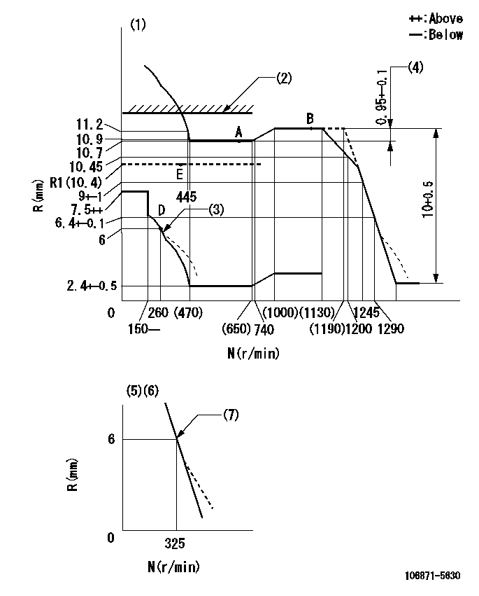
N:Pump speed
R:Rack position (mm)
(1)Tolerance for racks not indicated: +-0.05mm.
(2)Rack limit using the stop lever: SRL
(3)Damper spring setting: DL
(4)Rack difference between N = N1 and N = N2
(5)Variable speed specification: idling adjustment
(6)Fix the lever at the full-load position at delivery.
(7)Main spring setting
----------
SRL=12.4+-0.1mm DL=5.5-0.2mm N1=1100r/min N2=600r/min
----------
----------
SRL=12.4+-0.1mm DL=5.5-0.2mm N1=1100r/min N2=600r/min
----------
Speed control lever angle

F:Full speed
I:Idle
(1)Pump speed = aa
(2)Set the stopper bolt (fixed at full-load position at delivery.)
----------
aa=325r/min
----------
a=16deg+-5deg b=12deg+-5deg
----------
aa=325r/min
----------
a=16deg+-5deg b=12deg+-5deg
0000000901

F:Full load
I:Idle
(1)Stopper bolt setting
(2)Use the hole at R = aa
----------
aa=64.3mm
----------
a=18.5deg+-5deg b=30.5deg+-3deg
----------
aa=64.3mm
----------
a=18.5deg+-5deg b=30.5deg+-3deg
Stop lever angle
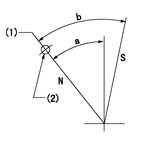
N:Pump normal
S:Stop the pump.
(1)Rack position = aa
(2)Use the pin at R = bb
----------
aa=12.4+-0.1mm bb=46mm
----------
a=36deg+-5deg b=38deg+-5deg
----------
aa=12.4+-0.1mm bb=46mm
----------
a=36deg+-5deg b=38deg+-5deg
0000001501 BCS

(A) Screw for precise adjustment
(B) Pre-adjustment screw
(C) Control rack, rack decrease direction
(D) Rack limit
1. Solenoid boost compensator adjustment
(1)Supply DC: V1 to the solenoid terminals and confirm solenoid operation.
(2)With the solenoid ON, calculate L1 from the value of R1. [L1 = La - (10.5 - R1) +-0.2]
(3)Adjust (B) to obtain L1.
(4)Assemble the solenoid to the governor.
(5)With the solenoid ON, readjust (B) so that R1 is within the allowance a.
(6)With the solenoid OFF, perform all governor adjustments except rack limit adjustment.
(7)Set the pump speed at N1 and turn the solenoid ON.
(8)Adjust (A) so that R1 is within the allowance range a.
(9)Set the pump speed at N1 and fix the load lever in the full position
(10)Turn the solenoid switch ON and OFF several times and confirm that the difference in rack positions is within L2.
(11)Set the rack limit.
(12)Stamp the solenoid valve.
----------
V1=24V N1=400r/min N2=0r/min R1=10.4mm a=+-0.5mm La=31mm L1=(30.9)+-0.2mm L2=3.5~5mm
----------
----------
V1=24V N1=400r/min N2=0r/min R1=10.4mm a=+-0.5mm La=31mm L1=(30.9)+-0.2mm L2=3.5~5mm
----------
Timing setting

(1)Pump vertical direction
(2)Position of the coupling's key groove at the beginning of injection of the No. 8 cylinder.
(3)-
(4)-
----------
----------
a=(90deg)
----------
----------
a=(90deg)
Information:
August 31, 2004
O-219
Priority PRODUCT IMPROVEMENT PROGRAM FOR REPLACINGTHE INJECTION ACTUATION PRESSURE SENSOR ON CERTAIN 3126E ENGINES
7755,1925 PI30676
This Program must be administered assoon as possible. When reporting the repair, use "PI30676" as the Partnumber and "7751" as the Group Number, "56" as the Warranty Claim DescriptionCode and "T" as the SIMS Description Code. Exception: If the repair isdone after failure, use "PI30676" as the Part Number, "7751" as the GroupNumber, "96" as the Warranty Claim Description Code, and "Z" as the SIMSDescription Code. The information supplied in this serviceletter may not be valid after the termination date of this program. Donot perform the work outlined in this Service Letter after the terminationdate without first contacting your Caterpillar product analyst.
COMPLETION DATE
TERMINATION DATE
February 28, 2005 August 31, 2005PROBLEM
Replace the injection actuation pressure sensorcertain 3126E engines. The old sensor may leak oil.AFFECTED PRODUCT
Model IdentificationNumber
3126E G3E230-497PARTS NEEDED
Qty
Part Number Description
1 2244536 SENSOR GP-PRACTION REQUIRED
Remove the 194-6726 Pressure Sensor and replaceit with part number 224-4536 Pressure Sensor.OWNER NOTIFICATION
U.S. and Canadian owners will receive the attachedOwner Notification.SERVICE CLAIM ALLOWANCES
Caterpillar Dealer Suggested Customer Suggested
Parts Labor Hrs Parts LaborHrs Parts LaborHrs
100% 1.0 0 0 0 0
This is a 1.0-hour job. U.S. and Canadian Dealers Only - Eligibledealers may enter a Type 2 SIMS ReportPARTS DISPOSITION
Handle the parts in accordance with your WarrantyBulletin on warranty parts handling.MAKE EVERY EFFORT TO COMPLETE THIS PROGRAMAS SOON AS POSSIBLE.Attach. (Owner Notification)COPY OF OWNER NOTIFICATION FOR U.S. AND CANADIAN OWNERS
XYZ Corporation
3240 Arrow Drive
Anywhere, YZ 99999PRIORITY - THE INJECTION ACTUATION PRESSURESENSOR NEEDS TO BE REPLACED.MODELS INVOLVED - CERTAIN 3126E ENGINESDear Caterpillar Product Owner:A new injection actuation pressure sensor needsto be installed on the products listed below. The current sensor may leakoil. You will not be charged for the service performed.Contact your local Caterpillar dealer immediatelyto schedule this service. The dealer will advise you of the time requiredto complete this service. Please refer the dealer to their Service Letterdated August 31, 2004 when scheduling this service.We regret the inconvenience this may causeyou, but urge you to have this service performed as soon as possible toprevent unscheduled downtime.Caterpillar Inc.
Identification #(s)Attached to August 31, 2004 Service Letter
Have questions with 106871-5630?
Group cross 106871-5630 ZEXEL
Nissan-Diesel
Nissan-Diesel
106871-5630
9 400 611 911
1671397874
INJECTION-PUMP ASSEMBLY
RG8
RG8