Information injection-pump assembly
BOSCH
9 400 618 170
9400618170
ZEXEL
106871-5520
1068715520
NISSAN-DIESEL
1680197566
1680197566

Rating:
Cross reference number
BOSCH
9 400 618 170
9400618170
ZEXEL
106871-5520
1068715520
NISSAN-DIESEL
1680197566
1680197566
Zexel num
Bosch num
Firm num
Name
Calibration Data:
Adjustment conditions
Test oil
1404 Test oil ISO4113 or {SAEJ967d}
1404 Test oil ISO4113 or {SAEJ967d}
Test oil temperature
degC
40
40
45
Nozzle and nozzle holder
105780-8250
Bosch type code
1 688 901 101
Nozzle
105780-0120
Bosch type code
1 688 901 990
Nozzle holder
105780-2190
Opening pressure
MPa
20.7
Opening pressure
kgf/cm2
211
Injection pipe
Outer diameter - inner diameter - length (mm) mm 8-3-600
Outer diameter - inner diameter - length (mm) mm 8-3-600
Overflow valve
131425-0120
Overflow valve opening pressure
kPa
157
123
191
Overflow valve opening pressure
kgf/cm2
1.6
1.25
1.95
Tester oil delivery pressure
kPa
255
255
255
Tester oil delivery pressure
kgf/cm2
2.6
2.6
2.6
RED3 control unit part number
407910-3
960
RED3 rack sensor specifications
mm
19
Direction of rotation (viewed from drive side)
Right R
Right R
Injection timing adjustment
Direction of rotation (viewed from drive side)
Right R
Right R
Injection order
1-8-7-5-
4-3-6-2
Pre-stroke
mm
4.7
4.67
4.73
Beginning of injection position
Governor side NO.1
Governor side NO.1
Difference between angles 1
Cal 1-8 deg. 45 44.75 45.25
Cal 1-8 deg. 45 44.75 45.25
Difference between angles 2
Cal 1-7 deg. 90 89.75 90.25
Cal 1-7 deg. 90 89.75 90.25
Difference between angles 3
Cal 1-5 deg. 135 134.75 135.25
Cal 1-5 deg. 135 134.75 135.25
Difference between angles 4
Cal 1-4 deg. 180 179.75 180.25
Cal 1-4 deg. 180 179.75 180.25
Difference between angles 5
Cal 1-3 deg. 225 224.75 225.25
Cal 1-3 deg. 225 224.75 225.25
Difference between angles 6
Cal 1-6 deg. 270 269.75 270.25
Cal 1-6 deg. 270 269.75 270.25
Difference between angles 7
Cyl.1-2 deg. 315 314.75 315.25
Cyl.1-2 deg. 315 314.75 315.25
Injection quantity adjustment
Rack position
(13.4)
Vist
V
1.85
1.85
1.85
Pump speed
r/min
650
650
650
Average injection quantity
mm3/st.
137
135
139
Max. variation between cylinders
%
0
-4
4
Basic
*
Injection quantity adjustment_02
Rack position
(8.4)
Vist
V
2.6
2.5
2.7
Pump speed
r/min
335
335
335
Average injection quantity
mm3/st.
14
12
16
Max. variation between cylinders
%
0
-10
10
Test data Ex:
Governor adjustment

(1)Adjusting range
(2)Step response time
(N): Speed of the pump
(L): Load
(theta) Advance angle
(Srd1) Step response time 1
(Srd2) Step response time 2
1. Adjusting conditions for the variable timer
(1)Adjust the clearance between the pickup and the protrusion to L.
----------
L=1-0.2mm N4=800r/min C4=(9deg) t1=1.7--sec. t2=1.7--sec.
----------
N1=400r/min N2=1000++r/min N3=- C1=9+-0.3deg C2=3.5++deg C3=- P1=0kPa(0kgf/cm2) P2=294kPa(3kgf/cm2) P3=392kPa(4kgf/cm2) R01=0/4load R02=4/4load R03=4/4load
----------
L=1-0.2mm N4=800r/min C4=(9deg) t1=1.7--sec. t2=1.7--sec.
----------
N1=400r/min N2=1000++r/min N3=- C1=9+-0.3deg C2=3.5++deg C3=- P1=0kPa(0kgf/cm2) P2=294kPa(3kgf/cm2) P3=392kPa(4kgf/cm2) R01=0/4load R02=4/4load R03=4/4load
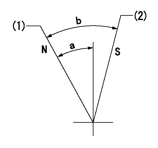
Speed control lever angle

N:Pump normal
S:Stop the pump.
(1)Rack position = aa
(2)Rack position bb
----------
aa=20mm bb=1mm
----------
a=27deg+-5deg b=37deg+-5deg
----------
aa=20mm bb=1mm
----------
a=27deg+-5deg b=37deg+-5deg
0000000901

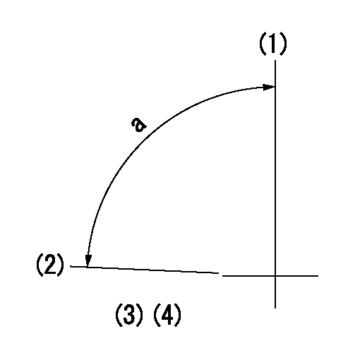
(1)Pump vertical direction
(2)Position of the coupling's key groove at the beginning of injection of the No. 8 cylinder.
(3)-
(4)-
----------
----------
a=(90deg)
----------
----------
a=(90deg)
Stop lever angle

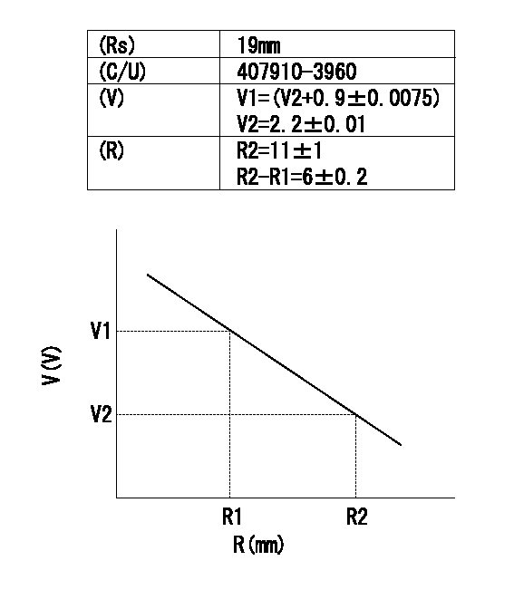
(Rs) rack sensor specifications
(C/U) control unit part number
(V) Rack sensor output voltage
(R) Rack position (mm)
1. Confirming governor output characteristics (rack 19 mm, span 6 mm)
(1)When the output voltages of the rack sensor are V1 and V2, check that the rack positions R1 and R2 in the table above are satisfied.
----------
----------
----------
----------
Information:
The information supplied in this service letter may not be valid after the termination date of this program. Do not perform the work outlined in this Service Letter after the termination date without first contacting your Caterpillar product analyst.
This Program can only be administered after a failure occurs. The decision whether to apply the Program is made by the dealer. When reporting the repair, use "PS0852" as the Part Number and "7755" as the Group Number. Use "96" as the Warranty Claim Description Code and use "Z" as the SIMS Description Code.
This Revised Service Letter replaces the June 22, 1995 (Revised July 1996) Service Letter. Changes have been made to the TERMINATION DATE.
Termination Date
June 30, 1997Problem
The fuel injector tip may fail on certain 3406E Truck Engines.
Affected Product
Model & Identification Number
3406E (5EK1812-14203)
Parts Needed
6 - 0R4893 Injector Group (reman part number for 1171148) (used on 435-5EK1-1820 HP ratings)or6 - 0R4894 Injector Group (reman part number for 1188010) (used on 355-5EK1-1820, 375-5EK1-1820, 375-5EK1-1820, 435-5EK1821-Up, 455, and 475 HP ratings)or6 - 0R4895 Injector Group (reman part number for 1187929) (used on 355-5EK1821-Up, 375-5EK1821-Up, and 410 HP ratings)Action Required
See attached rework procedure.
Service Claim Allowances
Labor should be claimed in accordance with labor times listed in the 3406E Time Requirement Guide.
Parts Disposition
Handle the parts in accordance with your Warranty Bulletin on warranty parts handling.
Attach.(Rework Procedure)Rework Procedure
1. Remove the necessary air piping, air cleaners, valve covers, Jake Brakes, and rocker arm assemblies.2. Before removing fuel injectors from engine, be sure to drain fuel from fuel system. The recommended procedure is to blow compressed air through system via the fuel filter air bleed cap. Remove the fuel injectors from the engine. Immediately clean off excess engine oil and place the fuel injectors in individual clean plastic bags. Use care to prevent dirt from entering the fuel passages in the side of the injector.3. Wrap each injector individually with padding. Be sure to provide adequate padding around the injectors to prevent damage to the electrical terminals and nozzle during shipment. Pack the injectors in a sturdy box for immediate shipment back to Caterpillar. (See PARTS DISPOSITION.)4. If the tip of the injector is cracked, inspect top of cylinder and injector bore for foreign material. If the tip is missing, inspect the cylinder head and turbocharger for foreign material. Also inspect the injector for a screen that may have fallen from the removed injector.5. Lubricate the two larger o-ring seals with engine oil and install the injectors. Tighten the injector hold down bolt to a torque of 55 N m (41 ft lb).6. Adjust the valves, injectors, and Jake Brakes if so equipped. Complete the assembly.7. Prime the fuel system as described in Systems Operation Testing and Adjusting, SENR5578, page 69, "Fuel Priming Procedure".8. Stamp the engine block with the letters "PS0852".