Information injection-pump assembly
BOSCH
F 01G 09U 09S
f01g09u09s
ZEXEL
106871-5381
1068715381

Rating:
Service parts 106871-5381 INJECTION-PUMP ASSEMBLY:
1.
_
7.
COUPLING PLATE
8.
_
9.
_
11.
Nozzle and Holder
16600-97119
12.
Open Pre:MPa(Kqf/cm2)
15.7{160}/22.6{230}
14.
NOZZLE
Include in #1:
106871-5381
as INJECTION-PUMP ASSEMBLY
Cross reference number
BOSCH
F 01G 09U 09S
f01g09u09s
ZEXEL
106871-5381
1068715381
Zexel num
Bosch num
Firm num
Name
Calibration Data:
Adjustment conditions
Test oil
1404 Test oil ISO4113 or {SAEJ967d}
1404 Test oil ISO4113 or {SAEJ967d}
Test oil temperature
degC
40
40
45
Nozzle and nozzle holder
105780-8250
Bosch type code
1 688 901 101
Nozzle
105780-0120
Bosch type code
1 688 901 990
Nozzle holder
105780-2190
Opening pressure
MPa
20.7
Opening pressure
kgf/cm2
211
Injection pipe
Outer diameter - inner diameter - length (mm) mm 8-3-600
Outer diameter - inner diameter - length (mm) mm 8-3-600
Overflow valve
131425-0120
Overflow valve opening pressure
kPa
157
123
191
Overflow valve opening pressure
kgf/cm2
1.6
1.25
1.95
Tester oil delivery pressure
kPa
255
255
255
Tester oil delivery pressure
kgf/cm2
2.6
2.6
2.6
RED3 control unit part number
407910-3
960
RED3 rack sensor specifications
mm
19
Direction of rotation (viewed from drive side)
Right R
Right R
Injection timing adjustment
Direction of rotation (viewed from drive side)
Right R
Right R
Injection order
1-8-7-5-
4-3-6-2
Pre-stroke
mm
4.7
4.67
4.73
Beginning of injection position
Governor side NO.1
Governor side NO.1
Difference between angles 1
Cal 1-8 deg. 45 44.75 45.25
Cal 1-8 deg. 45 44.75 45.25
Difference between angles 2
Cal 1-7 deg. 90 89.75 90.25
Cal 1-7 deg. 90 89.75 90.25
Difference between angles 3
Cal 1-5 deg. 135 134.75 135.25
Cal 1-5 deg. 135 134.75 135.25
Difference between angles 4
Cal 1-4 deg. 180 179.75 180.25
Cal 1-4 deg. 180 179.75 180.25
Difference between angles 5
Cal 1-3 deg. 225 224.75 225.25
Cal 1-3 deg. 225 224.75 225.25
Difference between angles 6
Cal 1-6 deg. 270 269.75 270.25
Cal 1-6 deg. 270 269.75 270.25
Difference between angles 7
Cyl.1-2 deg. 315 314.75 315.25
Cyl.1-2 deg. 315 314.75 315.25
Injection quantity adjustment
Rack position
(13.4)
Vist
V
1.85
1.85
1.85
Pump speed
r/min
650
650
650
Average injection quantity
mm3/st.
137
135
139
Max. variation between cylinders
%
0
-4
4
Basic
*
Injection quantity adjustment_02
Rack position
(8.4)
Vist
V
2.6
2.5
2.7
Pump speed
r/min
335
335
335
Average injection quantity
mm3/st.
14
12
16
Max. variation between cylinders
%
0
-10
10
Governor adjustment
Pump speed
r/min
750--
Advance angle
deg.
0
0
0
Remarks
Q = 155+-2 (mm3/st) / N = 650 (r/min), beginning of effect
Q = 155+-2 (mm3/st) / N = 650 (r/min), beginning of effect
Governor adjustment_02
Pump speed
r/min
700
Advance angle
deg.
0.3
Remarks
Q=155+-2(mm3/st)/N=650 (r/min)
Q=155+-2(mm3/st)/N=650 (r/min)
Governor adjustment_03
Pump speed
r/min
(750)
Advance angle
deg.
2
1.7
2.3
Remarks
Q=155+-2(mm3/st)/N=650 (r/min)
Q=155+-2(mm3/st)/N=650 (r/min)
Governor adjustment_04
Pump speed
r/min
850
Advance angle
deg.
2
1.7
2.3
Remarks
Q=87+-2(mm3/st)/N=850(r/min)
Q=87+-2(mm3/st)/N=850(r/min)
Governor adjustment_05
Pump speed
r/min
1080
Advance angle
deg.
7
6.7
7.3
Remarks
Q = 146+-2 (mm3/st) / N = 1100 (r/min), end of effect
Q = 146+-2 (mm3/st) / N = 1100 (r/min), end of effect
Test data Ex:
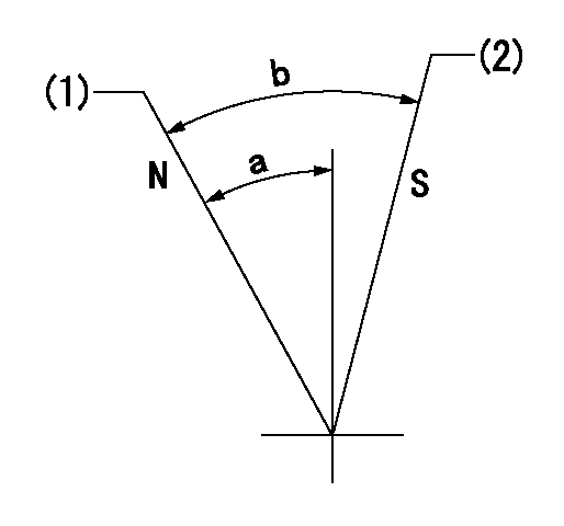
Speed control lever angle

N:Pump normal
S:Stop the pump.
(1)Rack position = aa
(2)Rack position bb
----------
aa=20mm bb=1mm
----------
a=27deg+-5deg b=37deg+-5deg
----------
aa=20mm bb=1mm
----------
a=27deg+-5deg b=37deg+-5deg
0000000901

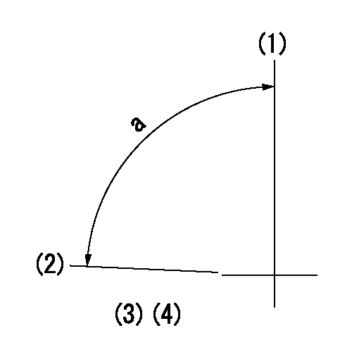
(1)Pump vertical direction
(2)Position of the coupling's key groove at the beginning of injection of the No. 8 cylinder.
(3)-
(4)-
----------
----------
a=(90deg)
----------
----------
a=(90deg)
Stop lever angle

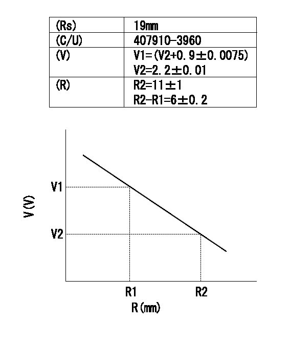
(Rs) rack sensor specifications
(C/U) control unit part number
(V) Rack sensor output voltage
(R) Rack position (mm)
1. Confirming governor output characteristics (rack 19 mm, span 6 mm)
(1)When the output voltages of the rack sensor are V1 and V2, check that the rack positions R1 and R2 in the table above are satisfied.
----------
----------
----------
----------
Information:
Caterpillar: Confidential Yellow
PSP FOR REPLACING ERODED CYLINDER HEAD INJECTOR SLEEVES IN CERTAIN IT14B INTEGRATED TOOLCARRIERS; E110B, E120B, E200B, EL2 00B, 213B, 214B, 224B, E240B, EL240B EXCAVATORS; 446 BACKHOE LOADERS; AND 3114 AND 3116 INDUSTRIAL AND GENERATOR SET EN GINES - PS0456 - US, CANADA, CACO, LTD COFA - REVISED 10/90
The information supplied in this service letter may not be valid after the termination date of this program. Do not perform the work outlined in this Service Letter after the termination date without first contacting your Caterpillar product analyst.
(Revised October 1990) U-130 A-88 AU-86.1 1100, 1290 PS0456 This Program can only be administered after a failure occurs. The decision whether to apply the Program is made by the dealer. When reporting the repair, use "PS0456" as Part Number, "7755" as Group Number, and "96" as Description Code. If this Program is administered on E200B or EL200B Excavators, it is recommended that the June 22, 1990 Service Letter - PS4442 be done at the same time. This Revised Service Letter replaces the June 25, 1990 Service Letter. Changes have been made to add Affected Product. Termination Date
June 30, 1991
Problem
The fuel injector sleeves in the cylinder head of certain IT14B Integrated Toolcarriers; E110B, E120B, E200B, EL200B, 213B, 214B, 224B, E240B, and EL240B Excavators; 446 Backhoe Loaders; CB-434, CP-563, and CS-563 Compactors; AP-1050 Asphalt Pavers; and 3114 and 3116 Industrial and Generator Set Engines are subject to pitting and erosion due to fuel cavitation between the injector and the sleeve. The sleeves may pit or crack through, allowing fuel to contaminate the coolant. Coolant contaminated with fuel may also damage the radiator and coolant hoses.
Affected Product
Model Identification Number IT14B 3NJ1-42 E110B 8MF1-151 E120B 6JF1-212 E200B* 6KF1-439 6KG1-249 EL200B* 7DF1-986 213B 1EJ1-233, 236-245, 247, 248 214B