Information injection-pump assembly
ZEXEL
106871-5211
1068715211

Rating:
Service parts 106871-5211 INJECTION-PUMP ASSEMBLY:
1.
_
7.
COUPLING PLATE
8.
_
9.
_
11.
Nozzle and Holder
16600-97078
12.
Open Pre:MPa(Kqf/cm2)
17.7{180}/22.6{230}
15.
NOZZLE SET
Include in #1:
106871-5211
as INJECTION-PUMP ASSEMBLY
Cross reference number
ZEXEL
106871-5211
1068715211
Zexel num
Bosch num
Firm num
Name
106871-5211
INJECTION-PUMP ASSEMBLY
Calibration Data:
Adjustment conditions
Test oil
1404 Test oil ISO4113 or {SAEJ967d}
1404 Test oil ISO4113 or {SAEJ967d}
Test oil temperature
degC
40
40
45
Nozzle and nozzle holder
105780-8140
Bosch type code
EF8511/9A
Nozzle
10580-0000
Bosch type code
DN12SD12T
Nozzle holder
105780-2080
Bosch type code
EF8511/9
Opening pressure
MPa
17.2
Opening pressure
kgf/cm2
175
Injection pipe
Outer diameter - inner diameter - length (mm) mm 8-3-600
Outer diameter - inner diameter - length (mm) mm 8-3-600
Overflow valve
132424-0620
Overflow valve opening pressure
kPa
157
123
191
Overflow valve opening pressure
kgf/cm2
1.6
1.25
1.95
Tester oil delivery pressure
kPa
157
157
157
Tester oil delivery pressure
kgf/cm2
1.6
1.6
1.6
Direction of rotation (viewed from drive side)
Right R
Right R
Injection timing adjustment
Direction of rotation (viewed from drive side)
Right R
Right R
Injection order
1-8-7-5-
4-3-6-2
Pre-stroke
mm
3.9
3.85
3.95
Beginning of injection position
Governor side NO.1
Governor side NO.1
Difference between angles 1
Cal 1-8 deg. 45 44.5 45.5
Cal 1-8 deg. 45 44.5 45.5
Difference between angles 2
Cal 1-7 deg. 90 89.5 90.5
Cal 1-7 deg. 90 89.5 90.5
Difference between angles 3
Cal 1-5 deg. 135 134.5 135.5
Cal 1-5 deg. 135 134.5 135.5
Difference between angles 4
Cal 1-4 deg. 180 179.5 180.5
Cal 1-4 deg. 180 179.5 180.5
Difference between angles 5
Cal 1-3 deg. 225 224.5 225.5
Cal 1-3 deg. 225 224.5 225.5
Difference between angles 6
Cal 1-6 deg. 270 269.5 270.5
Cal 1-6 deg. 270 269.5 270.5
Difference between angles 7
Cyl.1-2 deg. 315 314.5 315.5
Cyl.1-2 deg. 315 314.5 315.5
Injection quantity adjustment
Adjusting point
A
Rack position
10.6
Pump speed
r/min
650
650
650
Average injection quantity
mm3/st.
139.5
138.5
140.5
Max. variation between cylinders
%
0
-4
4
Basic
*
Fixing the lever
*
Injection quantity adjustment_02
Adjusting point
D
Rack position
6.2+-0.5
Pump speed
r/min
235
235
235
Average injection quantity
mm3/st.
9.5
7.5
11.5
Max. variation between cylinders
%
0
-10
10
Fixing the rack
*
Injection quantity adjustment_03
Adjusting point
F
Rack position
-
Pump speed
r/min
100
100
100
Average injection quantity
mm3/st.
140
140
180
Fixing the lever
*
Remarks
After startup boost setting
After startup boost setting
Timer adjustment
Pump speed
r/min
750--
Advance angle
deg.
0
0
0
Remarks
Start
Start
Timer adjustment_02
Pump speed
r/min
700
Advance angle
deg.
0.3
Timer adjustment_03
Pump speed
r/min
(780)
Advance angle
deg.
1
0.7
1.3
Remarks
Measure the actual speed.
Measure the actual speed.
Timer adjustment_04
Pump speed
r/min
-
Advance angle
deg.
1
0.7
1.3
Remarks
Measure the actual speed.
Measure the actual speed.
Timer adjustment_05
Pump speed
r/min
1100
Advance angle
deg.
4.75
4.45
5.05
Remarks
Finish
Finish
Test data Ex:
Governor adjustment

N:Pump speed
R:Rack position (mm)
(1)Tolerance for racks not indicated: +-0.05mm.
(2)Excess fuel setting for starting: SXL
(3)Damper spring setting
(4)Variable speed specification: idling adjustment
(5)Fix the lever at the full-load position at delivery.
(6)Main spring setting
----------
SXL=11+-0.1mm
----------
----------
SXL=11+-0.1mm
----------
Speed control lever angle

F:Full speed
I:Idle
(1)Set the pump speed at aa
(2)Set the stopper bolt (fixed at full-load position at delivery.)
----------
aa=290r/min
----------
a=12deg+-5deg b=6.5deg+-5deg
----------
aa=290r/min
----------
a=12deg+-5deg b=6.5deg+-5deg
0000000901

F:Full load
I:Idle
(1)Stopper bolt setting
(2)Use the hole at R = aa
----------
aa=64.3mm
----------
a=18.5deg+-5deg b=28.5deg+-3deg
----------
aa=64.3mm
----------
a=18.5deg+-5deg b=28.5deg+-3deg
Stop lever angle
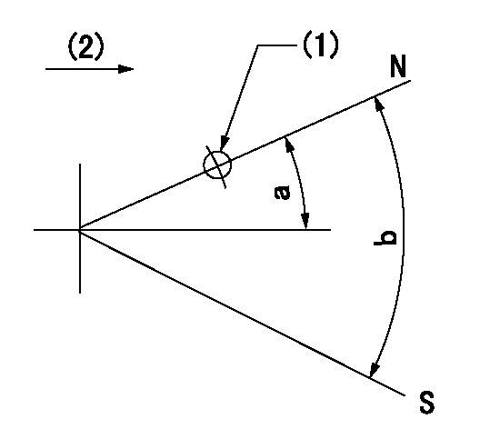
N:Pump normal
S:Stop the pump.
(1)Use the pin at R = aa
(2)Drive side
----------
aa=28mm
----------
a=12deg+-5deg b=64deg+-5eg
----------
aa=28mm
----------
a=12deg+-5deg b=64deg+-5eg
Timing setting

(1)Pump vertical direction
(2)Position of the coupling's key groove at the beginning of injection of the No. 8 cylinder.
(3)-
(4)-
----------
----------
a=(90deg)
----------
----------
a=(90deg)
Information:
Do not operate or work on this product unless you have read and understood the instruction and warnings in the relevant Operation and Maintenance Manuals and relevant service literature. Failure to follow the instructions or heed the warnings could result in injury or death. Proper care is your responsibility.
There have been instances of diagnostic code E931 - Aftertreatment#1 SCR Dosing Reagent Absolute Pressure : Low (4334-18 - Aftertreatment #1 DEF #1 Pressure (absolute) : Low – moderate severity) becoming active. This code can be generated by a blocked 495-1507 Diesel Exhaust Fluid Filter Gp, due to the filter not being replaced at the correct maintenance interval.The maintenance interval schedule for the DEF pump filter is every 1500 hours. Ensure that the filter is replaced at the correct service interval. Refer to Operation and Maintenance Manual, Maintenance Interval Schedule for the correct procedure.
Have questions with 106871-5211?
Group cross 106871-5211 ZEXEL
Nissan-Diesel
106871-5211
INJECTION-PUMP ASSEMBLY