Information injection-pump assembly
ZEXEL
106871-5160
1068715160
Rating:
Service parts 106871-5160 INJECTION-PUMP ASSEMBLY:
1.
_
7.
COUPLING PLATE
8.
_
9.
_
11.
Nozzle and Holder
16600-97079
12.
Open Pre:MPa(Kqf/cm2)
17.7{180}/22.6{230}
14.
NOZZLE
Include in #1:
106871-5160
as INJECTION-PUMP ASSEMBLY
Cross reference number
ZEXEL
106871-5160
1068715160
Zexel num
Bosch num
Firm num
Name
106871-5160
INJECTION-PUMP ASSEMBLY
Calibration Data:
Adjustment conditions
Test oil
1404 Test oil ISO4113 or {SAEJ967d}
1404 Test oil ISO4113 or {SAEJ967d}
Test oil temperature
degC
40
40
45
Nozzle and nozzle holder
105780-8140
Bosch type code
EF8511/9A
Nozzle
105780-0000
Bosch type code
DN12SD12T
Nozzle holder
105780-2080
Bosch type code
EF8511/9
Opening pressure
MPa
17.2
Opening pressure
kgf/cm2
175
Injection pipe
Outer diameter - inner diameter - length (mm) mm 8-3-600
Outer diameter - inner diameter - length (mm) mm 8-3-600
Overflow valve
132424-0620
Overflow valve opening pressure
kPa
157
123
191
Overflow valve opening pressure
kgf/cm2
1.6
1.25
1.95
RED3 control unit part number
157
157
157
RED3 rack sensor specifications
1.6
1.6
1.6
Direction of rotation (viewed from drive side)
Right R
Right R
Injection timing adjustment
Direction of rotation (viewed from drive side)
Right R
Right R
Injection order
1-8-7-5-
4-3-6-2
Pre-stroke
mm
3.9
3.85
3.95
Beginning of injection position
Governor side NO.1
Governor side NO.1
Difference between angles 1
Cal 1-8 deg. 45 44.5 45.5
Cal 1-8 deg. 45 44.5 45.5
Difference between angles 2
Cal 1-7 deg. 90 89.5 90.5
Cal 1-7 deg. 90 89.5 90.5
Difference between angles 3
Cal 1-5 deg. 135 134.5 135.5
Cal 1-5 deg. 135 134.5 135.5
Difference between angles 4
Cal 1-4 deg. 180 179.5 180.5
Cal 1-4 deg. 180 179.5 180.5
Difference between angles 5
Cal 1-3 deg. 225 224.5 225.5
Cal 1-3 deg. 225 224.5 225.5
Difference between angles 6
Cal 1-6 deg. 270 269.5 270.5
Cal 1-6 deg. 270 269.5 270.5
Difference between angles 7
Cyl.1-2 deg. 315 314.5 315.5
Cyl.1-2 deg. 315 314.5 315.5
Injection quantity adjustment
Adjusting point
A
Rack position
10.6
Pump speed
r/min
600
600
600
Average injection quantity
mm3/st.
177
176
178
Max. variation between cylinders
%
0
-4
4
Basic
*
Fixing the lever
*
Boost pressure
kPa
37.3
37.3
Boost pressure
mmHg
280
280
Injection quantity adjustment_02
Adjusting point
C
Rack position
4.8+-0.5
Pump speed
r/min
235
235
235
Average injection quantity
mm3/st.
12
10
14
Max. variation between cylinders
%
0
-10
10
Fixing the rack
*
Boost pressure
kPa
0
0
0
Boost pressure
mmHg
0
0
0
Injection quantity adjustment_03
Adjusting point
E
Rack position
11.7+-0.
1
Pump speed
r/min
100
100
100
Average injection quantity
mm3/st.
140
140
Fixing the lever
*
Boost pressure
kPa
37.3
37.3
Boost pressure
mmHg
280
280
Rack limit
*
Boost compensator adjustment
Pump speed
r/min
400
400
400
Rack position
R1(9.5)
Boost pressure
kPa
6.7
6.7
6.7
Boost pressure
mmHg
50
50
50
Boost compensator adjustment_02
Pump speed
r/min
400
400
400
Rack position
R1+1
Boost pressure
kPa
14.7
13.4
16
Boost pressure
mmHg
110
100
120
Boost compensator adjustment_03
Pump speed
r/min
400
400
400
Rack position
11.7+-0.
1
Boost pressure
kPa
24
24
24
Boost pressure
mmHg
180
180
180
Timer adjustment
Pump speed
r/min
700
Advance angle
deg.
0.3
Timer adjustment_02
Pump speed
r/min
-
Advance angle
deg.
0.8
0.5
1.1
Remarks
Measure the actual speed.
Measure the actual speed.
Timer adjustment_03
Pump speed
r/min
-
Advance angle
deg.
0.8
0.5
1.1
Remarks
Measure the actual speed.
Measure the actual speed.
Timer adjustment_04
Pump speed
r/min
1000
Remarks
Measure the actual advance angle.
Measure the actual advance angle.
Timer adjustment_05
Pump speed
r/min
1080
Advance angle
deg.
4.5
4.2
4.8
Remarks
Finish
Finish
Test data Ex:
Governor adjustment
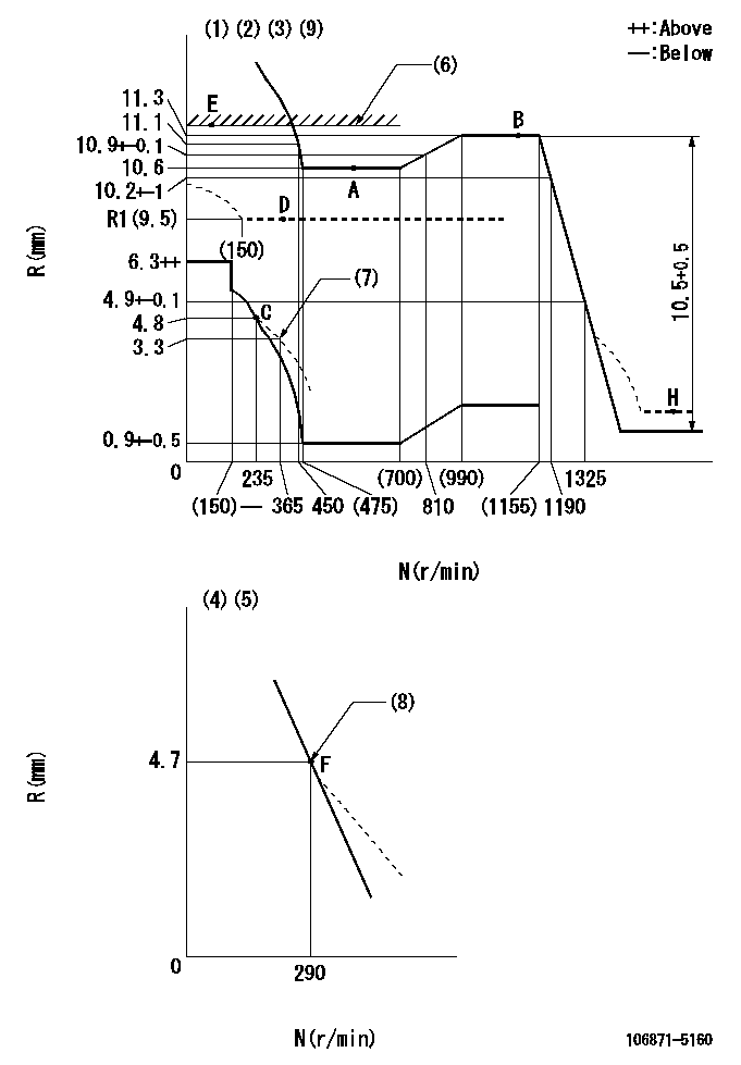
N:Pump speed
R:Rack position (mm)
(1)Lever ratio: RT
(2)Target shim dimension: TH
(3)Tolerance for racks not indicated: +-0.05mm.
(4)Variable speed specification: idling adjustment
(5)Fix the lever at the full-load position at delivery.
(6)Rack limit using the stop lever: R1
(7)Damper spring setting
(8)Main spring setting
(9)Perform governor adjustment at an ambient temperature of at least 15 deg C (boost compensator start spring is shape memory alloy).
----------
RT=1 TH=2.5mm R1=11.7+-0.1mm
----------
----------
RT=1 TH=2.5mm R1=11.7+-0.1mm
----------
Speed control lever angle

F:Full speed
I:Idle
(1)Pump speed = aa
(2)Set the stopper bolt (fixed at full-load position at delivery.)
----------
aa=290r/min
----------
a=14deg+-5deg b=6deg+-5deg
----------
aa=290r/min
----------
a=14deg+-5deg b=6deg+-5deg
0000000901
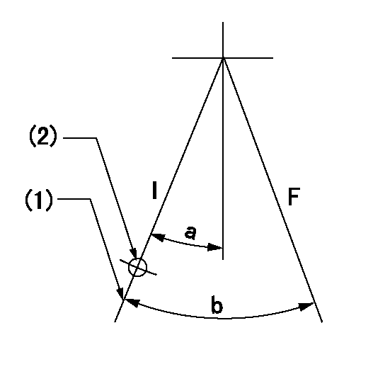
F:Full load
I:Idle
(1)Stopper bolt setting
(2)Use the hole at R = aa
----------
aa=64.3mm
----------
a=18.5deg+-5deg b=35deg+-3deg
----------
aa=64.3mm
----------
a=18.5deg+-5deg b=35deg+-3deg
Stop lever angle
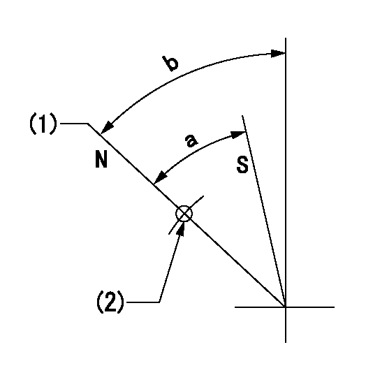
N:Pump normal
S:Stop the pump.
(1)Rack position = aa
(2)Use the pin at R = bb
----------
aa=11.7+-0.1mm bb=52mm
----------
a=(33.5deg)+-5deg b=(37.5deg)+-5deg
----------
aa=11.7+-0.1mm bb=52mm
----------
a=(33.5deg)+-5deg b=(37.5deg)+-5deg
Timing setting
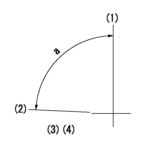
(1)Pump vertical direction
(2)Position of the coupling's key groove at the beginning of injection of the No. 8 cylinder.
(3)-
(4)-
----------
----------
a=(90deg)
----------
----------
a=(90deg)
Information:
Illustration 4 g01633558
(5) 326-7322 Bracket As (13) 250-3895 Spacer (14) 8T-4896 Hard Washer (15) 4L-6459 Bolt
Install the new 326-7322 Bracket As (5) by using four new 250-3895 Spacers (13), four new 4L-6459 Bolts (15), and four new 8T-4896 Hard Washers (14) in the same place where the muffler was previously installed. Refer to Illustration 4.
Illustration 5 g01633569
(4) 326-7321 Connector As (11) 249-3108 Isolation Mount (12) 7X-0618 Hard Washer (16) 8T-4244 Nut (17) 8T-7930 Bolt (19) 8T-4223 Hard Washer
Install the new 326-7321 Connector As (4) on bracket assembly (5) by using three new 249-3108 Isolation Mounts (11), three new 8T-7930 Bolts (17), six new 7X-0618 Hard Washers (12), three new 8T-4223 Hard Washers (19), and three new 8T-4244 Nuts (16). Refer to Illustration 5.
Illustration 6 g01633576
(2) 326-7333 Brace (7) 326-7334 Brace (11) 249-3108 Isolation Mount (12) 7X-0618 Hard Washer (16) 8T-4244 Nut (18) 8T-4176 Bolt (19) 8T-4223 Hard Washer
Install a new 326-7333 Brace (2) and a new 326-7334 Brace (7) to connector assembly (4) by using two new 249-3108 Isolation Mounts (11), two new 8T-4176 Bolts (18), four new 7X-0618 Hard Washers (12), two new 8T-4223 Hard Washers (19) and two new 8T-4244 Nuts (16). Refer to Illustration 6.
Illustration 7 g01633578
(1) 326-7315 Diesel Particulate Filter Gp
Install the new 326-7315 Diesel Particulate Filter Gp (1) onto connector assembly (4). The weight of the diesel particulate filter group is approximately 72.5 kg (160 lb). Refer to Illustration 7.
Illustration 8 g01633590
(9) 326-7320 Filter Clamp Assembly (16) 8T-4244 Nut (19) 8T-4223 Hard Washer (20) 8T-4910 Bolt
Install two new 326-7320 Filter Clamp As (9) by using eight new 8T-4223 Hard Washers (19), four new 8T-4910 Bolts (20) and four new 8T-4244 Nuts (16). Refer to Illustration 8.
Illustration 9 g01633633
(10) 195-3068 Ejector (22) 5P-0597 Hose Clamp (23) 273-3000 Hose (24) 233-7182 Tube
Install the new 195-3068 Ejector (10) to the diesel particulate filter. Refer to Illustration 9.
Install the new 273-3000 Hose (23), and the new 233-7182 Tube (24) to the ejector by using four new 5P-0597 Hose Clamps (22). Refer to Illustration 9.
Illustration 10 g01633714
(6) 326-7328 Tube As (8) 328-8875 Adaptor As (25) 141-1480 Clamp As (27) 202-1838 V-Band Clamp (28) 243-2973 Bellows
Install the new 326-7328 Tube As (6) to the inlet module tube of the diesel particulate filter by using a new 141-1480 Clamp As (25). Refer to Illustration 10.
Install the new 243-2973 Bellows (28) to tube assembly (6) by using a new 202-1838 V-Band
Have questions with 106871-5160?
Group cross 106871-5160 ZEXEL
Nissan-Diesel
Nissan-Diesel
Nissan-Diesel
Nissan-Diesel
Nissan-Diesel
Nissan-Diesel
106871-5160
INJECTION-PUMP ASSEMBLY