Information injection-pump assembly
ZEXEL
106871-5130
1068715130
Rating:
Cross reference number
ZEXEL
106871-5130
1068715130
Zexel num
Bosch num
Firm num
Name
106871-5130
INJECTION-PUMP ASSEMBLY
Calibration Data:
Adjustment conditions
Test oil
1404 Test oil ISO4113 or {SAEJ967d}
1404 Test oil ISO4113 or {SAEJ967d}
Test oil temperature
degC
40
40
45
Nozzle and nozzle holder
105780-8140
Bosch type code
EF8511/9A
Nozzle
105780-0000
Bosch type code
DN12SD12T
Nozzle holder
105780-2080
Bosch type code
EF8511/9
Opening pressure
MPa
17.2
Opening pressure
kgf/cm2
175
Injection pipe
Outer diameter - inner diameter - length (mm) mm 8-3-600
Outer diameter - inner diameter - length (mm) mm 8-3-600
Overflow valve
132424-0620
Overflow valve opening pressure
kPa
157
123
191
Overflow valve opening pressure
kgf/cm2
1.6
1.25
1.95
Tester oil delivery pressure
kPa
157
157
157
Tester oil delivery pressure
kgf/cm2
1.6
1.6
1.6
Direction of rotation (viewed from drive side)
Right R
Right R
Injection timing adjustment
Direction of rotation (viewed from drive side)
Right R
Right R
Injection order
1-8-7-5-
4-3-6-2
Pre-stroke
mm
3.65
3.6
3.7
Beginning of injection position
Governor side NO.1
Governor side NO.1
Difference between angles 1
Cal 1-8 deg. 45 44.5 45.5
Cal 1-8 deg. 45 44.5 45.5
Difference between angles 2
Cal 1-7 deg. 90 89.5 90.5
Cal 1-7 deg. 90 89.5 90.5
Difference between angles 3
Cal 1-5 deg. 135 134.5 135.5
Cal 1-5 deg. 135 134.5 135.5
Difference between angles 4
Cal 1-4 deg. 180 179.5 180.5
Cal 1-4 deg. 180 179.5 180.5
Difference between angles 5
Cal 1-3 deg. 225 224.5 225.5
Cal 1-3 deg. 225 224.5 225.5
Difference between angles 6
Cal 1-6 deg. 270 269.5 270.5
Cal 1-6 deg. 270 269.5 270.5
Difference between angles 7
Cyl.1-2 deg. 315 314.5 315.5
Cyl.1-2 deg. 315 314.5 315.5
Injection quantity adjustment
Adjusting point
A
Rack position
10
Pump speed
r/min
700
700
700
Average injection quantity
mm3/st.
123
122
124
Max. variation between cylinders
%
0
-4
4
Basic
*
Fixing the lever
*
Injection quantity adjustment_02
Adjusting point
C
Rack position
6.9+-0.5
Pump speed
r/min
280
280
280
Average injection quantity
mm3/st.
11.5
9.5
13.5
Max. variation between cylinders
%
0
-10
10
Fixing the rack
*
Injection quantity adjustment_03
Adjusting point
D
Rack position
-
Pump speed
r/min
100
100
100
Average injection quantity
mm3/st.
145
125
165
Fixing the lever
*
Remarks
After startup boost setting
After startup boost setting
Timer adjustment
Pump speed
r/min
500--
Advance angle
deg.
0
0
0
Remarks
Start
Start
Timer adjustment_02
Pump speed
r/min
450
Advance angle
deg.
0.5
Timer adjustment_03
Pump speed
r/min
1100
Advance angle
deg.
3.5
3
4
Remarks
Finish
Finish
Test data Ex:
Governor adjustment
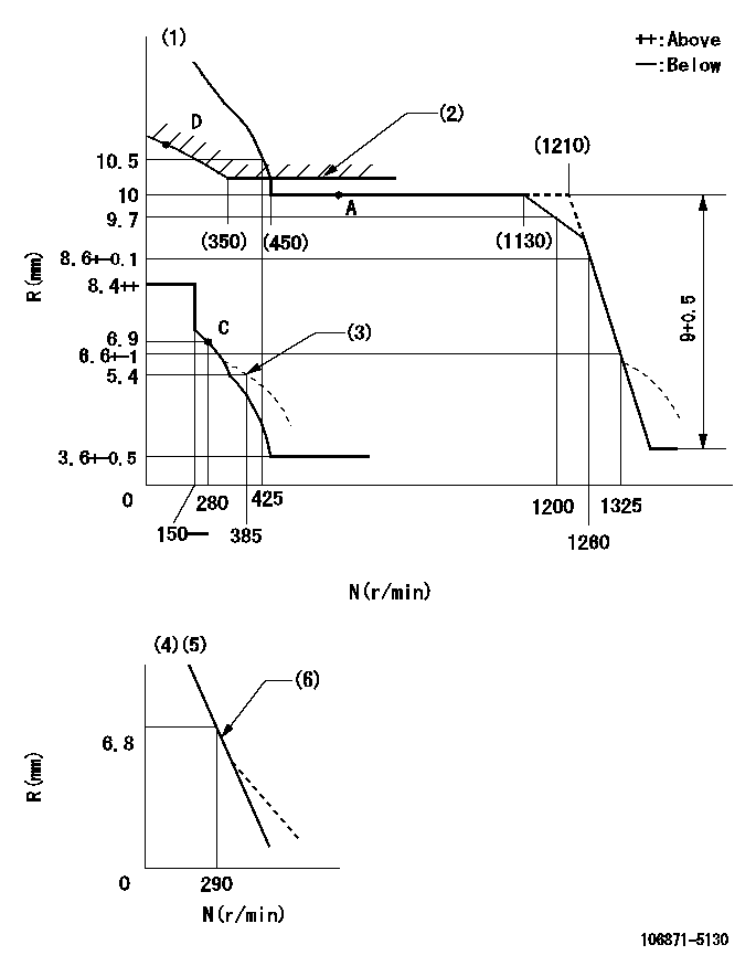
N:Pump speed
R:Rack position (mm)
(1)Tolerance for racks not indicated: +-0.05mm.
(2)Excess fuel setting for starting: SXL (N = N1)
(3)Damper spring setting
(4)Variable speed specification: idling adjustment
(5)Fix the lever at the full-load position at delivery.
(6)Main spring setting
----------
SXL=10.2+-0.1mm N1=400r/min
----------
----------
SXL=10.2+-0.1mm N1=400r/min
----------
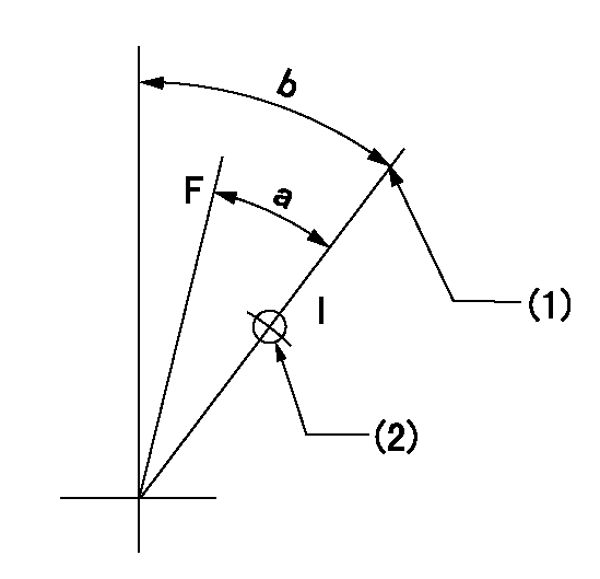
Speed control lever angle

F:Full speed
I:Idle
(1)Pump speed = aa
(2)Set the stopper bolt (fixed at full-load position at delivery.)
----------
aa=290r/min
----------
a=13.5deg+-5deg b=5deg+-5deg
----------
aa=290r/min
----------
a=13.5deg+-5deg b=5deg+-5deg
0000000901
F:Full load
I:Idle
(1)Stopper bolt setting
(2)Use the hole at R = aa
----------
aa=46mm
----------
a=24deg+-3deg b=33deg+-5deg
----------
aa=46mm
----------
a=24deg+-3deg b=33deg+-5deg
Stop lever angle
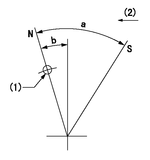
N:Pump normal
S:Stop the pump.
(1)Use the pin at R = aa
(2)Drive side
----------
aa=28mm
----------
a=64deg+-5deg b=20deg+-5deg
----------
aa=28mm
----------
a=64deg+-5deg b=20deg+-5deg
Timing setting
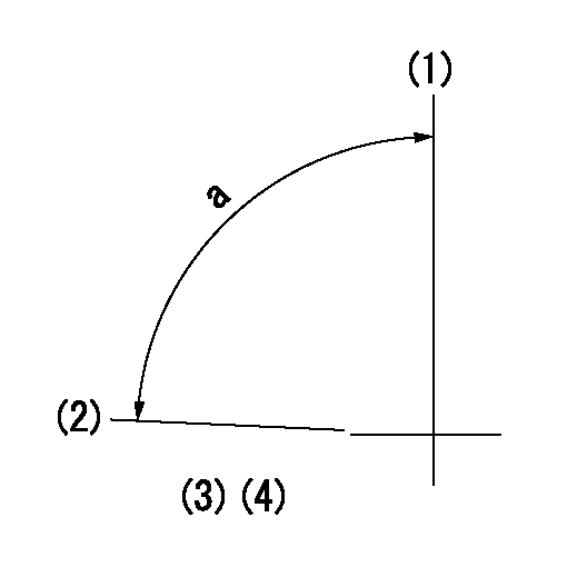
(1)Pump vertical direction
(2)Position of the coupling's key groove at the beginning of injection of the No. 8 cylinder.
(3)-
(4)-
----------
----------
a=(90deg)
----------
----------
a=(90deg)
Information:
Introduction
The problem that is identified below does not have a known permanent solution. Until a permanent solution is known, use the solution that is identified below.Problem
Some of the 3408E engines and 3412E engines in the above listed machines may experience hard starting or low power due to oil that is leaking past the poppet valve in the injector. The oil leakage is caused by the operating conditions at either low idle or high idle. Excessive oil leakage can reduce actuation pressure to the fuel injector. This may prevent fuel injection.Solution
Electrical shock hazard. The electronic unit injector system uses 90-120 volts.
Follow the proper troubleshooting procedure for the correct engine. If the problem is not located and the symptoms that are listed above continue, remove the engine valve covers. Electrically disable the injectors. Crank the engine. Watch the spill ports of the injector for oil leakage. A small amount of oil leakage is acceptable. A continuous stream of oil may mean leakage from the poppet valve. Excessive leakage from the poppet valve may prevent fuel injection.Note: Normal oil pressure during cranking should be 5 MPa (725 psi). Oil pressure below 5 MPa (725 psi) may indicate excessive oil leakage in injectors. Do not replace the oil pump. Service personnel should replace the injectors that have a continuous flow of oil from the oil ports. Injectors that have a continuous flow of oil and injectors that are within the guidelines of warranty can be returned. Injectors that do not have a continuous flow of oil should not be replaced. Injectors that do not have a continuous flow of oil should not be returned.Note: For additional information on the operation of Hydraulic Electronic Unit Injectors HEUI, refer to CD, RENR1390.
Illustration 1 g01308874
(1) Oil drain portThe oil drain ports are located underneath the solenoid. This will direct the oil flow downward. Some oil may also leak from the rectangular slots at the side of the solenoid. Excess oil leakage will still be visible on the cylinder head.
Have questions with 106871-5130?
Group cross 106871-5130 ZEXEL
Nissan-Diesel
Nissan-Diesel
Nissan-Diesel
106871-5130
INJECTION-PUMP ASSEMBLY