Information injection-pump assembly
ZEXEL
106871-5090
1068715090
Rating:
Cross reference number
ZEXEL
106871-5090
1068715090
Zexel num
Bosch num
Firm num
Name
106871-5090
INJECTION-PUMP ASSEMBLY
Calibration Data:
Adjustment conditions
Test oil
1404 Test oil ISO4113 or {SAEJ967d}
1404 Test oil ISO4113 or {SAEJ967d}
Test oil temperature
degC
40
40
45
Nozzle and nozzle holder
105780-8140
Bosch type code
EF8511/9A
Nozzle
105780-0000
Bosch type code
DN12SD12T
Nozzle holder
105780-2080
Bosch type code
EF8511/9
Opening pressure
MPa
17.2
Opening pressure
kgf/cm2
175
Injection pipe
Outer diameter - inner diameter - length (mm) mm 8-3-600
Outer diameter - inner diameter - length (mm) mm 8-3-600
Overflow valve
132424-0620
Overflow valve opening pressure
kPa
157
123
191
Overflow valve opening pressure
kgf/cm2
1.6
1.25
1.95
Tester oil delivery pressure
kPa
157
157
157
Tester oil delivery pressure
kgf/cm2
1.6
1.6
1.6
Direction of rotation (viewed from drive side)
Right R
Right R
Injection timing adjustment
Direction of rotation (viewed from drive side)
Right R
Right R
Injection order
1-8-7-5-
4-3-6-2
Pre-stroke
mm
3.65
3.6
3.7
Beginning of injection position
Governor side NO.1
Governor side NO.1
Difference between angles 1
Cal 1-8 deg. 45 44.5 45.5
Cal 1-8 deg. 45 44.5 45.5
Difference between angles 2
Cal 1-7 deg. 90 89.5 90.5
Cal 1-7 deg. 90 89.5 90.5
Difference between angles 3
Cal 1-5 deg. 135 134.5 135.5
Cal 1-5 deg. 135 134.5 135.5
Difference between angles 4
Cal 1-4 deg. 180 179.5 180.5
Cal 1-4 deg. 180 179.5 180.5
Difference between angles 5
Cal 1-3 deg. 225 224.5 225.5
Cal 1-3 deg. 225 224.5 225.5
Difference between angles 6
Cal 1-6 deg. 270 269.5 270.5
Cal 1-6 deg. 270 269.5 270.5
Difference between angles 7
Cyl.1-2 deg. 315 314.5 315.5
Cyl.1-2 deg. 315 314.5 315.5
Injection quantity adjustment
Adjusting point
A
Rack position
10
Pump speed
r/min
700
700
700
Average injection quantity
mm3/st.
123
122
124
Max. variation between cylinders
%
0
-4
4
Basic
*
Fixing the lever
*
Injection quantity adjustment_02
Adjusting point
C
Rack position
6.9+-0.5
Pump speed
r/min
280
280
280
Average injection quantity
mm3/st.
11.5
9.5
13.5
Max. variation between cylinders
%
0
-10
10
Fixing the rack
*
Injection quantity adjustment_03
Adjusting point
D
Rack position
-
Pump speed
r/min
100
100
100
Average injection quantity
mm3/st.
145
125
165
Fixing the lever
*
Remarks
After startup boost setting
After startup boost setting
Timer adjustment
Pump speed
r/min
500--
Advance angle
deg.
0
0
0
Remarks
Start
Start
Timer adjustment_02
Pump speed
r/min
450
Advance angle
deg.
0.5
Timer adjustment_03
Pump speed
r/min
1100
Advance angle
deg.
3.5
3
4
Remarks
Finish
Finish
Test data Ex:
Governor adjustment
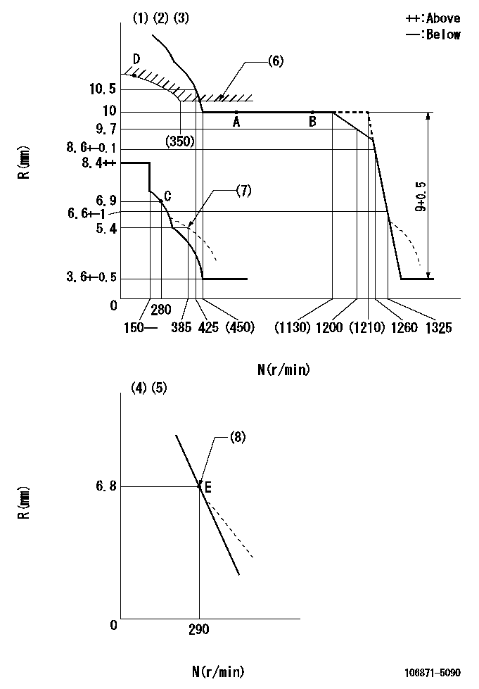
N:Pump speed
R:Rack position (mm)
(1)Lever ratio: RT
(2)Target shim dimension: TH
(3)Tolerance for racks not indicated: +-0.05mm.
(4)Variable speed specification: idling adjustment
(5)Fix the lever at the full-load position at delivery.
(6)Excess fuel setting for starting: SXL (N = N1)
(7)Damper spring setting
(8)Main spring setting
----------
RT=1 TH=2.1mm SXL=10.2+-0.1mm N1=400r/min
----------
----------
RT=1 TH=2.1mm SXL=10.2+-0.1mm N1=400r/min
----------
Speed control lever angle

F:Full speed
I:Idle
(1)Pump speed = aa
(2)Set the stopper bolt (fixed at full-load position at delivery.)
----------
aa=290r/min
----------
a=13.5deg+-5deg b=5deg+-5deg
----------
aa=290r/min
----------
a=13.5deg+-5deg b=5deg+-5deg
0000000901

F:Full load
I:Idle
(1)Stopper bolt setting
(2)Use the hole at R = aa
----------
aa=64.3mm
----------
a=18.5deg+-5deg b=24deg+-3deg
----------
aa=64.3mm
----------
a=18.5deg+-5deg b=24deg+-3deg
Stop lever angle

N:Pump normal
S:Stop the pump.
(1)Drive side
(2)Use the pin at R = aa
----------
aa=28mm
----------
a=12deg+-5deg b=64deg+-5deg
----------
aa=28mm
----------
a=12deg+-5deg b=64deg+-5deg
Timing setting

(1)Pump vertical direction
(2)Position of the coupling's key groove at the beginning of injection of the No. 8 cylinder.
(3)-
(4)-
----------
----------
a=(90deg)
----------
----------
a=(90deg)
Information:
Procedure
Illustration 1 g06220548
(1) TC Mark (Flywheel Housing)
(2) TC Mark (Flywheel)
Remove valve cover, and injector and rocker arm. Bring the piston of cylinder 4 to TDC.
Illustration 2 g06220554
(3) Dial Gauge
(4) Valve
(5) O-ring
Remove the #4 exhaust valve bridge arm and valve spring. Insert a small O-ring (5) so the valve does not fall into the cylinder.
Set dial gauge (3) on the tip of the valve (4).
Illustration 3 g06220569
(6) Tri - Square
(7) Flywheel Housing
(8) Flywheel
Illustration 4 g06220573
(7) Flywheel Housing
(8) Flywheel
(9) Reference Line
Turn the flywheel counterclockwise and measure the position where the tip of the valve is the highest.
Stop the flywheel at the position where the tip of the valve is the highest. Put a tri - square (6) on the flywheel housing (7) and the flywheel (8) and draw a reference line (9).Do not drop the valve (4) into the cylinder. When measuring the highest position of the tip of the valve, do not rotate the flywheel clockwise. If you go past the highest point of the valve, back up the flywheel slightly and measure the highest point of the valve. The reference line (9) indicates the TDC of the crankshaft.
Illustration 5 g06220579
Rotation Sensor Signal Interface Unit
Application: Use for reading rotation sensor signal.
(1) 9V Battery
(2) Switch
(3) 3-Terminal Regulator
(4) LED
(5) Clip (Red)
(6) Clip (Black)
(A) for Panasonic
(B) for Denso
(C) for Bosch cam angle
(D) for Bosch crank angle
((E)) Connector Side
(a) +9 V
(b) Signal
(c) GND
(d) +5 V
(e) Signal
(f) GND
Schematic to build Rotation Sensor Signal Interface.
Illustration 6 g06220581
(10) Rotation Sensor Signal Interface (Tool not available. Schematic to build tool available. Refer to Step 6.
(11) Tester
Illustration 7 g06220587
(12) Ground Terminal
(13) Output Terminal
(14) Crankshaft Position Sensor
Connect a connector of the rotation sensor signal interface unit (10) to the crankshaft position sensor (14). Connect each clip of the rotation sensor signal interface unit (10) to the same test lead color of the tester (11). Switch on the rotation sensor signal interface unit (10).
Illustration 8 g06220590
(15) Pulsar Gear
(16) 14th Tooth
(17) Missing Teeth
Turn the flywheel and make sure that the voltage of the crankshaft position sensor goes from 0→ 5 V or 5 → 0 V.
Rotate the flywheel and align the crankshaft position sensor to the part of the pulsar gear (15) that is missing teeth (17). The 14th tooth (16) from the missing teeth is standard.
Slowly turn flywheel counterclockwise and stop flywheel at the point where needle of the tester changes momentarily from 0 → 5 V, the 14th tooth.That point is where the crankshaft position sensor detects TDC.
Illustration 9 g06220608
(18) Crankshaft TDC
(19) Detection Point of Crankshaft Position Sensor TDC
Illustration 10 g06220612
(20) Interval
Set the tri - square (6) on the reference line (9) on the flywheel housing side and mark the detection point of crankshaft position sensor TDC (19) on the flywheel.
Measure the interval (20) between the crankshaft TDC (18) and the detection point of the crankshaft position sensor TDC (19).
Calculation of fuel injection timing correction 1.0 mm (0.039 in.): 0.321°.Corrected Angle = 0.321° X actual interval
Overwrite the injection timing correction value on the engine ecm registration website refer to REHS9707, "Registering Diesel Particulate Filter (DPF), Diesel Oxidation Catalyst (DOC),
Have questions with 106871-5090?
Group cross 106871-5090 ZEXEL
Nissan-Diesel
Nissan-Diesel
Nissan-Diesel
Nissan-Diesel
Nissan-Diesel
Nissan-Diesel
Nissan-Diesel
Nissan-Diesel
Nissan-Diesel
106871-5090
INJECTION-PUMP ASSEMBLY