Information injection-pump assembly
ZEXEL
106871-5001
1068715001

Rating:
Cross reference number
ZEXEL
106871-5001
1068715001
Zexel num
Bosch num
Firm num
Name
106871-5001
INJECTION-PUMP ASSEMBLY
Calibration Data:
Adjustment conditions
Test oil
1404 Test oil ISO4113 or {SAEJ967d}
1404 Test oil ISO4113 or {SAEJ967d}
Test oil temperature
degC
40
40
45
Nozzle and nozzle holder
105780-8140
Bosch type code
EF8511/9A
Nozzle
105780-0000
Bosch type code
DN12SD12T
Nozzle holder
105780-2080
Bosch type code
EF8511/9
Opening pressure
MPa
17.2
Opening pressure
kgf/cm2
175
Injection pipe
Outer diameter - inner diameter - length (mm) mm 8-3-600
Outer diameter - inner diameter - length (mm) mm 8-3-600
Overflow valve
134424-4220
Overflow valve opening pressure
kPa
157
123
191
Overflow valve opening pressure
kgf/cm2
1.6
1.25
1.95
Tester oil delivery pressure
kPa
157
157
157
Tester oil delivery pressure
kgf/cm2
1.6
1.6
1.6
Direction of rotation (viewed from drive side)
Right R
Right R
Injection timing adjustment
Direction of rotation (viewed from drive side)
Right R
Right R
Injection order
1-8-7-5-
4-3-6-2
Pre-stroke
mm
3.65
3.6
3.7
Beginning of injection position
Governor side NO.1
Governor side NO.1
Difference between angles 1
Cal 1-8 deg. 45 44.5 45.5
Cal 1-8 deg. 45 44.5 45.5
Difference between angles 2
Cal 1-7 deg. 90 89.5 90.5
Cal 1-7 deg. 90 89.5 90.5
Difference between angles 3
Cal 1-5 deg. 135 134.5 135.5
Cal 1-5 deg. 135 134.5 135.5
Difference between angles 4
Cal 1-4 deg. 180 179.5 180.5
Cal 1-4 deg. 180 179.5 180.5
Difference between angles 5
Cal 1-3 deg. 225 224.5 225.5
Cal 1-3 deg. 225 224.5 225.5
Difference between angles 6
Cal 1-6 deg. 270 269.5 270.5
Cal 1-6 deg. 270 269.5 270.5
Difference between angles 7
Cyl.1-2 deg. 315 314.5 315.5
Cyl.1-2 deg. 315 314.5 315.5
Injection quantity adjustment
Adjusting point
A
Rack position
9.6
Pump speed
r/min
700
700
700
Average injection quantity
mm3/st.
115.7
114.7
116.7
Max. variation between cylinders
%
0
-4
4
Basic
*
Fixing the lever
*
Injection quantity adjustment_02
Adjusting point
B
Rack position
9.6
Pump speed
r/min
1100
1100
1100
Average injection quantity
mm3/st.
120
116
124
Max. variation between cylinders
%
0
-4
4
Fixing the lever
*
Injection quantity adjustment_03
Adjusting point
C
Rack position
6.7+-0.5
Pump speed
r/min
235
235
235
Average injection quantity
mm3/st.
10.4
8.4
12.4
Max. variation between cylinders
%
0
-10
10
Fixing the rack
*
Injection quantity adjustment_04
Adjusting point
D
Rack position
-
Pump speed
r/min
100
100
100
Average injection quantity
mm3/st.
155
155
Fixing the lever
*
Remarks
After startup boost setting
After startup boost setting
Timer adjustment
Pump speed
r/min
1000
Advance angle
deg.
1.7
1.2
2.2
Timer adjustment_02
Pump speed
r/min
1100
Advance angle
deg.
5
4.5
5.5
Remarks
Finish
Finish
Test data Ex:
Governor adjustment
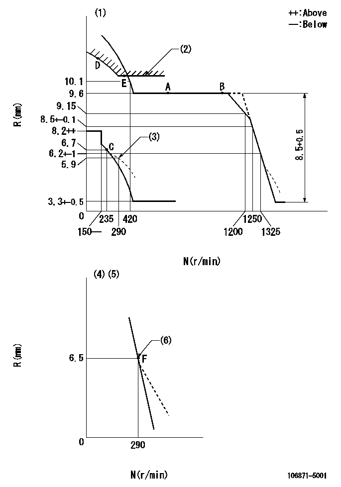
N:Pump speed
R:Rack position (mm)
(1)Tolerance for racks not indicated: +-0.05mm.
(2)Excess fuel setting for starting: SXL
(3)Damper spring setting
(4)Variable speed specification: idling adjustment
(5)Fix the lever at the full-load position at delivery.
(6)Main spring setting
----------
SXL=10.3+-0.1mm
----------
----------
SXL=10.3+-0.1mm
----------
Speed control lever angle

F:Full speed
I:Idle
(1)Pump speed = aa
(2)Set the stopper bolt (fixed at full-load position at delivery.)
----------
aa=290r/min
----------
a=(11deg)+-5deg b=5deg+-5deg
----------
aa=290r/min
----------
a=(11deg)+-5deg b=5deg+-5deg
0000000901

F:Full load
I:Idle
(1)Stopper bolt setting
(2)Use the hole at R = aa
----------
aa=64.3mm
----------
a=18.5deg+-5deg b=23.5deg+-3deg
----------
aa=64.3mm
----------
a=18.5deg+-5deg b=23.5deg+-3deg
Stop lever angle
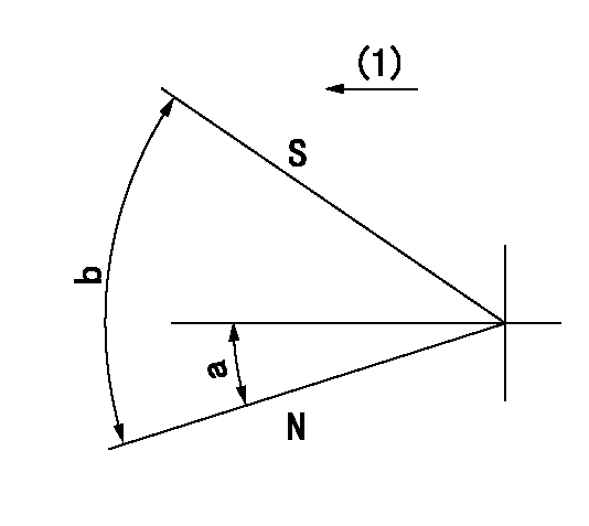
N:Pump normal
S:Stop the pump.
(1)Drive side
----------
----------
a=12deg+-5deg b=64deg+-5deg
----------
----------
a=12deg+-5deg b=64deg+-5deg
Timing setting

(1)Pump vertical direction
(2)Position of the coupling's key groove at the beginning of injection of the No. 8 cylinder.
(3)-
(4)-
----------
----------
a=(90deg)
----------
----------
a=(90deg)
Information:
Be sure all timing pins and bolts have been removed from timing holes before turning the crankshaft.
2. Remove the nuts and cap from the connecting rod. Push the piston and connecting rod up until the piston rings are out of cylinder liner. 3. Remove the connecting rod and piston (1) from engine. Keep the caps and bearings with their respective connecting rods.Install Pistons
1. Turn the crankshaft so the bearing journal is at bottom center for piston being installed.2. Put clean engine oil on crankshaft journal, connecting rod bearings, and the piston rings. 3. Put compressor (A) on top of liner, and install the piston and connecting rod with the "V" mark on piston in alignment with "V" mark on spacer plate. Put the connecting rod in position on crankshaft while pushing piston into liner. 4. Put clean engine oil on threads of connecting rod bolts. Install the caps on connecting rods. Install and tighten nuts to 30 3 lb.ft. (4.1 0.4 mkg). Put a mark across the nuts and bolts; and turn nuts clockwise 90° from marks as shown.
Make sure the number mark on side of cap is the same number and on the same side as the number mark on side of connecting rod.
end by: a) install oil pumpb) install cylinder head assembly
Have questions with 106871-5001?
Group cross 106871-5001 ZEXEL
106871-5001
INJECTION-PUMP ASSEMBLY