Information injection-pump assembly
ZEXEL
106871-4340
1068714340
Rating:
Cross reference number
ZEXEL
106871-4340
1068714340
Zexel num
Bosch num
Firm num
Name
Calibration Data:
Adjustment conditions
Test oil
1404 Test oil ISO4113 or {SAEJ967d}
1404 Test oil ISO4113 or {SAEJ967d}
Test oil temperature
degC
40
40
45
Nozzle and nozzle holder
105780-8140
Bosch type code
EF8511/9A
Nozzle
105780-0000
Bosch type code
DN12SD12T
Nozzle holder
105780-2080
Bosch type code
EF8511/9
Opening pressure
MPa
17.2
Opening pressure
kgf/cm2
175
Injection pipe
Outer diameter - inner diameter - length (mm) mm 8-3-600
Outer diameter - inner diameter - length (mm) mm 8-3-600
Overflow valve
132424-0620
Overflow valve opening pressure
kPa
157
157
157
Overflow valve opening pressure
kgf/cm2
1.6
1.6
1.6
Tester oil delivery pressure
kPa
157
157
157
Tester oil delivery pressure
kgf/cm2
1.6
1.6
1.6
Direction of rotation (viewed from drive side)
Right R
Right R
Injection timing adjustment
Direction of rotation (viewed from drive side)
Right R
Right R
Injection order
1-8-7-5-
4-3-6-2
Pre-stroke
mm
3.65
3.6
3.7
Beginning of injection position
Governor side No.1
Governor side No.1
Difference between angles 1
Cal 1-8 deg. 45 44.5 45.5
Cal 1-8 deg. 45 44.5 45.5
Difference between angles 2
Cal 1-7 deg. 90 89.5 90.5
Cal 1-7 deg. 90 89.5 90.5
Difference between angles 3
Cal 1-5 deg. 135 134.5 135.5
Cal 1-5 deg. 135 134.5 135.5
Difference between angles 4
Cal 1-4 deg. 180 179.5 180.5
Cal 1-4 deg. 180 179.5 180.5
Difference between angles 5
Cal 1-3 deg. 225 224.5 225.5
Cal 1-3 deg. 225 224.5 225.5
Difference between angles 6
Cal 1-6 deg. 270 269.5 270.5
Cal 1-6 deg. 270 269.5 270.5
Difference between angles 7
Cyl.1-2 deg. 315 314.5 315.5
Cyl.1-2 deg. 315 314.5 315.5
Injection quantity adjustment
Adjusting point
A
Rack position
9.7
Pump speed
r/min
700
700
700
Average injection quantity
mm3/st.
125.5
124.5
126.5
Max. variation between cylinders
%
0
-4
4
Basic
*
Fixing the lever
*
Injection quantity adjustment_02
Adjusting point
C
Rack position
6.1+-0.5
Pump speed
r/min
280
280
280
Average injection quantity
mm3/st.
11.5
9.5
13.5
Max. variation between cylinders
%
0
-10
10
Fixing the rack
*
Injection quantity adjustment_03
Adjusting point
D
Rack position
-
Pump speed
r/min
100
100
100
Average injection quantity
mm3/st.
130
130
150
Fixing the lever
*
Remarks
After startup boost setting
After startup boost setting
Timer adjustment
Pump speed
r/min
800--
Advance angle
deg.
0
0
0
Remarks
Start
Start
Timer adjustment_02
Pump speed
r/min
750
Advance angle
deg.
0.3
Timer adjustment_03
Pump speed
r/min
1100
Advance angle
deg.
4
3.7
4.3
Remarks
Finish
Finish
Test data Ex:
Governor adjustment
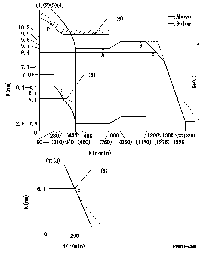
N:Pump speed
R:Rack position (mm)
(1)Adjust governor at speed not exceeding N = N1. Output voltage VR+-0.01 (V), speed N1 r/min, governor Vist = V1 (V)
(2)Tolerance for racks not indicated: +-0.05mm.
(3)Lever ratio: RT
(4)Target shim dimension: TH
(5)Excess fuel setting for starting: SXL (N = N2)
(6)Damper spring setting
(7)Variable speed specification: idling adjustment
(8)Fix the lever at the full-load position at delivery.
(9)Main spring setting
----------
N1=1710r/min RT=1 TH=2.8mm SXL=10.2+-0.1mm N2=400r/min
----------
----------
N1=1710r/min RT=1 TH=2.8mm SXL=10.2+-0.1mm N2=400r/min
----------
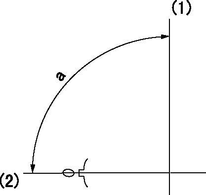
Speed control lever angle
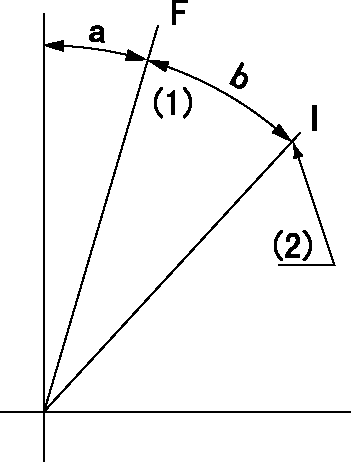
F:Full speed
I:Idle
(1)Set the stopper bolt (fixed at full-load position at delivery.)
(2)Pump speed = aa
----------
aa=290r/min
----------
a=(6deg)+-5deg b=(17deg)+-5deg
----------
aa=290r/min
----------
a=(6deg)+-5deg b=(17deg)+-5deg
0000000901

F:Full load
I:Idle
(1)Stopper bolt setting
(2)Use the hole at R = aa
----------
aa=64.3mm
----------
a=18.5deg+-5deg b=26.5deg+-3deg
----------
aa=64.3mm
----------
a=18.5deg+-5deg b=26.5deg+-3deg
Stop lever angle
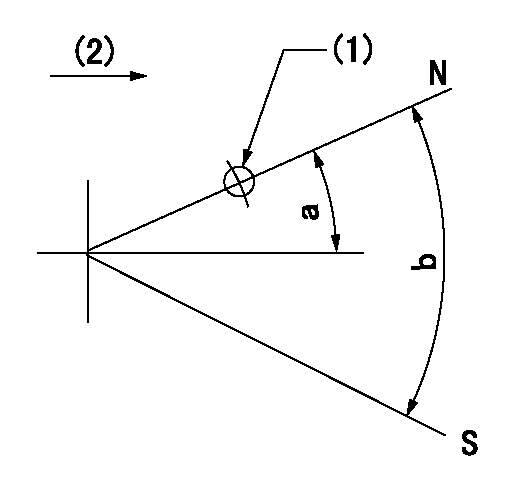
N:Pump normal
S:Stop the pump.
(1)Use the pin at R = aa
(2)Drive side
----------
aa=28mm
----------
a=12deg+-5deg b=64deg+-5deg
----------
aa=28mm
----------
a=12deg+-5deg b=64deg+-5deg
Timing setting
(1)Pump vertical direction
(2)Position of the coupling key groove at the beginning of injection of the No. 8 cylinder.
----------
----------
a=(90deg)
----------
----------
a=(90deg)
Information:
TERMINATION DATE
30Sep2013
PROBLEM
The existing fuel injectors can experience internal body cracks due to material inclusions and variability in the factory tightening procedure and/or the poppet sticking as a result of body and valve tolerancing on certain C32 marine engines. If the existing fuel injector fails it can result in complaints of misfire and/or low power.
AFFECTED PRODUCT
Model Identification Number
C32 RND00276-00339
RNE00126-00140
RNX00104-00110, 112, 115-136, 140, 145, 148-158, 162-165, 169-202, 206, 209-212, 214-217, 219-220, 222, 224-228, 232-238, 240-247, 250, 252-253, 257, 263, 265, 267-282, 284-285, 288-289, 291-305, 307, 310, 312-317, 320, 323, 325-329, 334-339, 341-343
RNY00102-00107, 119-120, 123-129, 135, 137, 154, 156-162, 171, 173, 183, 190-192, 196-200, 202-203, 205, 210-211, 213, 220-222, 225-226, 228-236, 238-242, 244-246, 248-249, 253-258, 260, 263-266, 269, 276, 280, 282, 285-286, 289-300, 302-305, 308-309, 312-315, 317-318, 327, 333-335, 337-349, 352, 356-358, 360-361, 363-366, 368, 370, 386, 391, 398-403, 406-408, 411-414, 417-419, 421-428, 443-448, 452-453, 456-457, 459-471, 474, 476, 478-489, 491-492, 497, 499-500, 502-507, 511-513, 516, 518-519, 521, 529-539, 541-542, 544, 546, 549, 551-554, 556-558, 571, 579-581, 585, 600-602, 606, 609-610, 613, 617-619, 621, 624-642, 644-665, 667, 672, 674, 676-677, 686-687, 695, 697-698, 700-702, 707-709, 711-728, 731-734, 737, 741, 746-748, 751-752, 755, 763, 765, 767, 777-782, 786-787, 794, 796, 798-799, 802, 804-820, 826, 829, 836, 842, 848, 859, 862, 866-867, 872-875, 886, 890-891, 894, 896-903, 909-910, 913-919, 925, 927, 929, 931, 934, 938, 952-954, 959-960, 973
RNZ00101-00158, 160, 162-181, 183-189, 191-220, 222-223, 225-231, 233-250, 252-253, 255-261, 263-270, 272-274, 276-294, 296-304, 306-447, 449-450, 452-456, 459-491, 493-496, 498-499, 502, 512-514
T3T00103-00104, 114, 134, 144-145, 147-150, 154-160, 164-213, 215-381, 383
PARTS NEEDED
Qty
Part Number Description
12 8S9191 BOLT
12 10R7231 FUEL INJECTOR GP
In order to allow equitable parts availability to all participating dealers, please limit your initial parts order to not exceed 7% of dealership population. This is an initial order recommendation only, and the ultimate responsibility for ordering the total number of parts needed to satisfy the program lies with the dealer.
ACTION REQUIRED
Take the following actions only after a failure occurs on one or more injectors in any of the engines listed in the Affected Product. A fuel injector is considered a failure if the following troubleshooting procedure is completed and the problem is not resolved.
1. Update the ECM software.
2. If still unable to produce advertised power, use publication SEBD9408 to determine if a change to FLS/FTS is required.
3. If still unable to produce advertised power, test the injector solenoid per RENR9326.
4. If still unable to produce advertised power, test the unit injector per SENR9773.
5. Replace injector(s) as required.
If one or more injectors fail replace all injectors at the time of repair.
Refer to Disassembly and Assembly, RENR8628 for the removal and installation procedure of the unit injector.
SERVICE CLAIM ALLOWANCES
Product smu/age whichever comes first Caterpillar Dealer Suggested Customer Suggested
Parts % Labor Hrs% Parts % Labor Hrs% Parts % Labor Hrs%
0-2000 hrs,
0-36 mo 100.0% 100.0% 0.0% 0.0% 0.0% 0.0%
This is a 10.0-hour job
For multiple engines that are serviced in a single vessel, please reference the other engine serial numbers in the claim story.
For before failure claims, please reference the after failure sister vessel engine serial