Information injection-pump assembly
ZEXEL
106871-4240
1068714240
Rating:
Cross reference number
ZEXEL
106871-4240
1068714240
Zexel num
Bosch num
Firm num
Name
Calibration Data:
Adjustment conditions
Test oil
1404 Test oil ISO4113 or {SAEJ967d}
1404 Test oil ISO4113 or {SAEJ967d}
Test oil temperature
degC
40
40
45
Nozzle and nozzle holder
105780-8140
Bosch type code
EF8511/9A
Nozzle
105780-0000
Bosch type code
DN12SD12T
Nozzle holder
105780-2080
Bosch type code
EF8511/9
Opening pressure
MPa
17.2
Opening pressure
kgf/cm2
175
Injection pipe
Outer diameter - inner diameter - length (mm) mm 8-3-600
Outer diameter - inner diameter - length (mm) mm 8-3-600
Overflow valve
132424-0620
Overflow valve opening pressure
kPa
157
123
191
Overflow valve opening pressure
kgf/cm2
1.6
1.25
1.95
Tester oil delivery pressure
kPa
157
157
157
Tester oil delivery pressure
kgf/cm2
1.6
1.6
1.6
Direction of rotation (viewed from drive side)
Right R
Right R
Injection timing adjustment
Direction of rotation (viewed from drive side)
Right R
Right R
Injection order
1-8-7-5-
4-3-6-2
Pre-stroke
mm
3.65
3.6
3.7
Beginning of injection position
Governor side NO.1
Governor side NO.1
Difference between angles 1
Cal 1-8 deg. 45 44.5 45.5
Cal 1-8 deg. 45 44.5 45.5
Difference between angles 2
Cal 1-7 deg. 90 89.5 90.5
Cal 1-7 deg. 90 89.5 90.5
Difference between angles 3
Cal 1-5 deg. 135 134.5 135.5
Cal 1-5 deg. 135 134.5 135.5
Difference between angles 4
Cal 1-4 deg. 180 179.5 180.5
Cal 1-4 deg. 180 179.5 180.5
Difference between angles 5
Cal 1-3 deg. 225 224.5 225.5
Cal 1-3 deg. 225 224.5 225.5
Difference between angles 6
Cal 1-6 deg. 270 269.5 270.5
Cal 1-6 deg. 270 269.5 270.5
Difference between angles 7
Cyl.1-2 deg. 315 314.5 315.5
Cyl.1-2 deg. 315 314.5 315.5
Injection quantity adjustment
Adjusting point
A
Rack position
9.7
Pump speed
r/min
700
700
700
Average injection quantity
mm3/st.
125.5
124.5
126.5
Max. variation between cylinders
%
0
-4
4
Basic
*
Fixing the lever
*
Injection quantity adjustment_02
Adjusting point
C
Rack position
6.1+-0.5
Pump speed
r/min
280
280
280
Average injection quantity
mm3/st.
11.5
9.5
13.5
Max. variation between cylinders
%
0
-10
10
Fixing the rack
*
Injection quantity adjustment_03
Adjusting point
D
Rack position
-
Pump speed
r/min
100
100
100
Average injection quantity
mm3/st.
130
130
150
Fixing the lever
*
Remarks
After startup boost setting
After startup boost setting
Timer adjustment
Pump speed
r/min
800--
Advance angle
deg.
0
0
0
Remarks
Start
Start
Timer adjustment_02
Pump speed
r/min
750
Advance angle
deg.
0.3
Timer adjustment_03
Pump speed
r/min
1100
Advance angle
deg.
4
3.7
4.3
Remarks
Finish
Finish
Test data Ex:
Governor adjustment
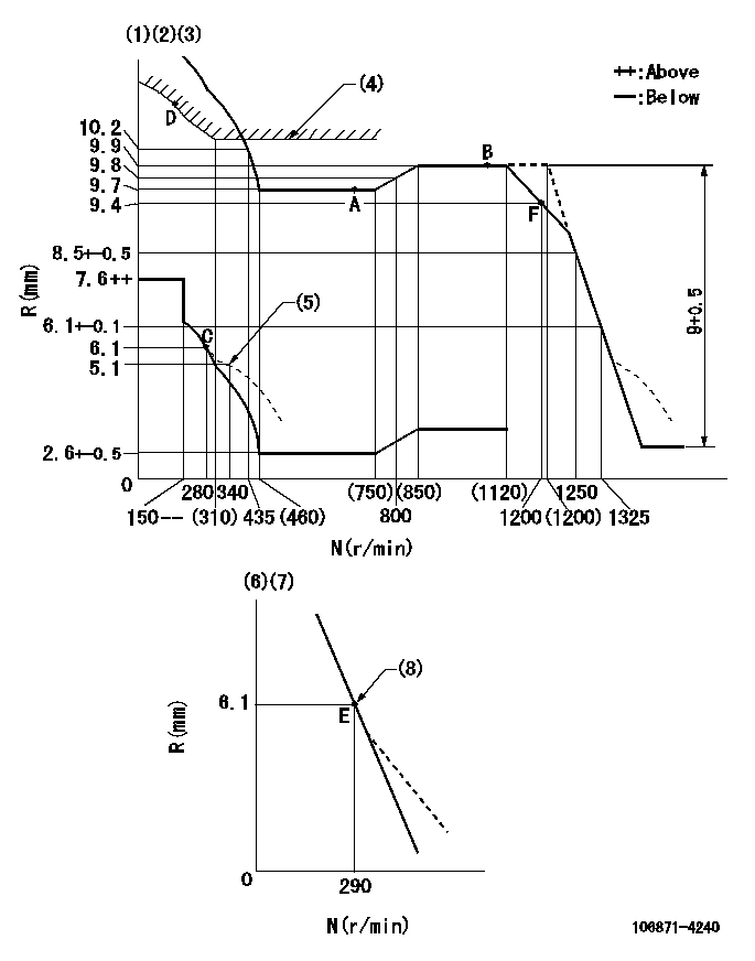
N:Pump speed
R:Rack position (mm)
(1)Lever ratio: RT
(2)Target shim dimension: TH
(3)Tolerance for racks not indicated: +-0.05mm.
(4)Excess fuel setting for starting: SXL (N = N1)
(5)Damper spring setting
(6)Variable speed specification: idling adjustment
(7)Fix the lever at the full-load position at delivery.
(8)Main spring setting
----------
RT=1 TH=2.8mm SXL=10.2+-0.1mm N1=400r/min
----------
----------
RT=1 TH=2.8mm SXL=10.2+-0.1mm N1=400r/min
----------
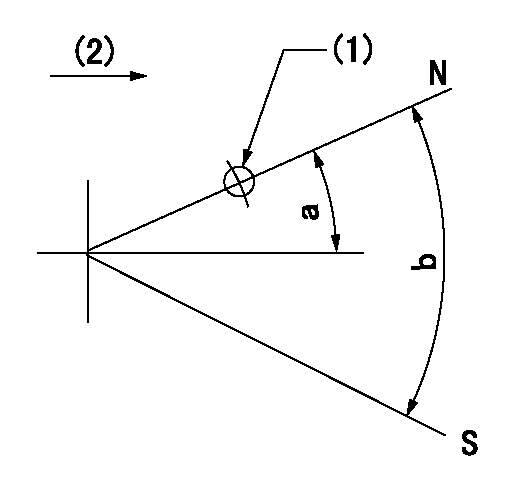
Speed control lever angle

F:Full speed
I:Idle
(1)Pump speed = aa
(2)Set the stopper bolt (fixed at full-load position at delivery.)
----------
aa=290r/min
----------
a=(4deg)+-5deg b=(13deg)+-5deg
----------
aa=290r/min
----------
a=(4deg)+-5deg b=(13deg)+-5deg
0000000901

F:Full load
I:Idle
(1)Stopper bolt setting
(2)Use the hole at R = aa
----------
aa=64.3mm
----------
a=18.5deg+-5deg b=26.5deg+-3deg
----------
aa=64.3mm
----------
a=18.5deg+-5deg b=26.5deg+-3deg
Stop lever angle
N:Pump normal
S:Stop the pump.
(1)Use the pin at R = aa
(2)Drive side
----------
aa=28mm
----------
a=12deg+-5deg b=64deg+-5deg
----------
aa=28mm
----------
a=12deg+-5deg b=64deg+-5deg
Timing setting

(1)Pump vertical direction
(2)Position of the coupling's key groove at the beginning of injection of the No. 8 cylinder.
(3)-
(4)-
----------
----------
a=(90deg)
----------
----------
a=(90deg)
Information:
ACTION REQUIRED
Take the following actions before or after a failure occurs on one or more injectors in any of the engines listed in this service letter.
- If one or more injectors fail it may be necessary to replace up to 6 injectors at the time of repair.
There will be situations when all 6 injectors do not have to be replaced. Refer to next paragraph to determine which injectors should be replaced.
- If an injector repair has previously been performed after approximately 01Oct07 on any of the listed engines, only the injectors that were not replaced at that time should be replaced. This should further be verified by comparing the injector serial numbers in the engine to a range of 3B115776403B to 3B11676551F9. Disregard the first and last two characters in the serial number (in this case "3B" and "3B" in the first serial number and "3B" and "F9" in the second serial number). The reason for verifying the serial number range is due to a batch change of the internal part that is failing. The change was made after serial number 3B11676551F9.
Only injectors falling within the range of 11577640-11676551 should be replaced.
- If the suspect injector can not be identified by using the automatic cylinder cutout test use the two methods below.
- First, run a manual cylinder cutout test at a high engine speed with some load on the engine. When the injector that has failed is cutout, the sound of the engine should be more normal as opposed to the loud knocking heard when the failed injector is active. The second method is to unplug the wiring harness at the valve cover base that sends current to the injector solenoids as well as the harness connection for the injection actuation pressure sensor. By making these disconnections, the fuel injectors will not fire and the HEUI pump will go to maximum actuation pressure. Then remove the valve cover and crank the engine. The injectors that have failed should expel more oil (from the HEUI System) than those that are not failed.
-Refer to RENR9579 for removal/install procedure of the unit injector.
-The serial number of all injectors replaced in an engine covered under this service letter must be documented in the claims story.
SERVICE CLAIM ALLOWANCES
Product smu/age