Information injection-pump assembly
ZEXEL
106871-4122
1068714122
Rating:
Cross reference number
ZEXEL
106871-4122
1068714122
Zexel num
Bosch num
Firm num
Name
Calibration Data:
Adjustment conditions
Test oil
1404 Test oil ISO4113 or {SAEJ967d}
1404 Test oil ISO4113 or {SAEJ967d}
Test oil temperature
degC
40
40
45
Nozzle and nozzle holder
105780-8140
Bosch type code
EF8511/9A
Nozzle
105780-0000
Bosch type code
DN12SD12T
Nozzle holder
105780-2080
Bosch type code
EF8511/9
Opening pressure
MPa
17.2
Opening pressure
kgf/cm2
175
Injection pipe
Outer diameter - inner diameter - length (mm) mm 8-3-600
Outer diameter - inner diameter - length (mm) mm 8-3-600
Overflow valve
134424-0820
Overflow valve opening pressure
kPa
127
107
147
Overflow valve opening pressure
kgf/cm2
1.3
1.1
1.5
Tester oil delivery pressure
kPa
157
157
157
Tester oil delivery pressure
kgf/cm2
1.6
1.6
1.6
Direction of rotation (viewed from drive side)
Right R
Right R
Injection timing adjustment
Direction of rotation (viewed from drive side)
Right R
Right R
Injection order
1-8-6-2-
7-5-4-3
Pre-stroke
mm
4.4
4.34
4.4
Beginning of injection position
Drive side NO.1
Drive side NO.1
Difference between angles 1
Cal 1-8 deg. 45 44.75 45.25
Cal 1-8 deg. 45 44.75 45.25
Difference between angles 2
Cal 1-6 deg. 90 89.75 90.25
Cal 1-6 deg. 90 89.75 90.25
Difference between angles 3
Cyl.1-2 deg. 135 134.75 135.25
Cyl.1-2 deg. 135 134.75 135.25
Difference between angles 4
Cal 1-7 deg. 180 179.75 180.25
Cal 1-7 deg. 180 179.75 180.25
Difference between angles 5
Cal 1-5 deg. 225 224.75 225.25
Cal 1-5 deg. 225 224.75 225.25
Difference between angles 6
Cal 1-4 deg. 270 269.75 270.25
Cal 1-4 deg. 270 269.75 270.25
Difference between angles 7
Cal 1-3 deg. 315 314.75 315.25
Cal 1-3 deg. 315 314.75 315.25
Injection quantity adjustment
Adjusting point
A
Rack position
9.5
Pump speed
r/min
500
500
500
Average injection quantity
mm3/st.
120
117
123
Max. variation between cylinders
%
0
-4
4
Fixing the lever
*
Injection quantity adjustment_02
Adjusting point
B
Rack position
9.6
Pump speed
r/min
700
700
700
Average injection quantity
mm3/st.
121.8
119.8
123.8
Max. variation between cylinders
%
0
-2
2
Basic
*
Fixing the lever
*
Injection quantity adjustment_03
Adjusting point
C
Rack position
10.4
Pump speed
r/min
1100
1100
1100
Average injection quantity
mm3/st.
145
142
148
Max. variation between cylinders
%
0
-4
4
Fixing the lever
*
Injection quantity adjustment_04
Adjusting point
D
Rack position
5.4+-0.5
Pump speed
r/min
225
225
225
Average injection quantity
mm3/st.
11.5
8.5
14.5
Max. variation between cylinders
%
0
-15
15
Fixing the rack
*
Injection quantity adjustment_05
Adjusting point
E
Rack position
-
Pump speed
r/min
100
100
100
Average injection quantity
mm3/st.
140
140
160
Fixing the lever
*
Remarks
After startup boost setting
After startup boost setting
Injection quantity adjustment_06
Adjusting point
F
Rack position
9.4+-0.5
Pump speed
r/min
1175
1175
1175
Average injection quantity
mm3/st.
126
121
131
Max. variation between cylinders
%
0
-4
4
Fixing the lever
*
Timer adjustment
Pump speed
r/min
750--
Advance angle
deg.
0
0
0
Remarks
Start
Start
Timer adjustment_02
Pump speed
r/min
700
Advance angle
deg.
0.5
Timer adjustment_03
Pump speed
r/min
1150
Advance angle
deg.
3
2.5
3.5
Remarks
Finish
Finish
Test data Ex:
Governor adjustment
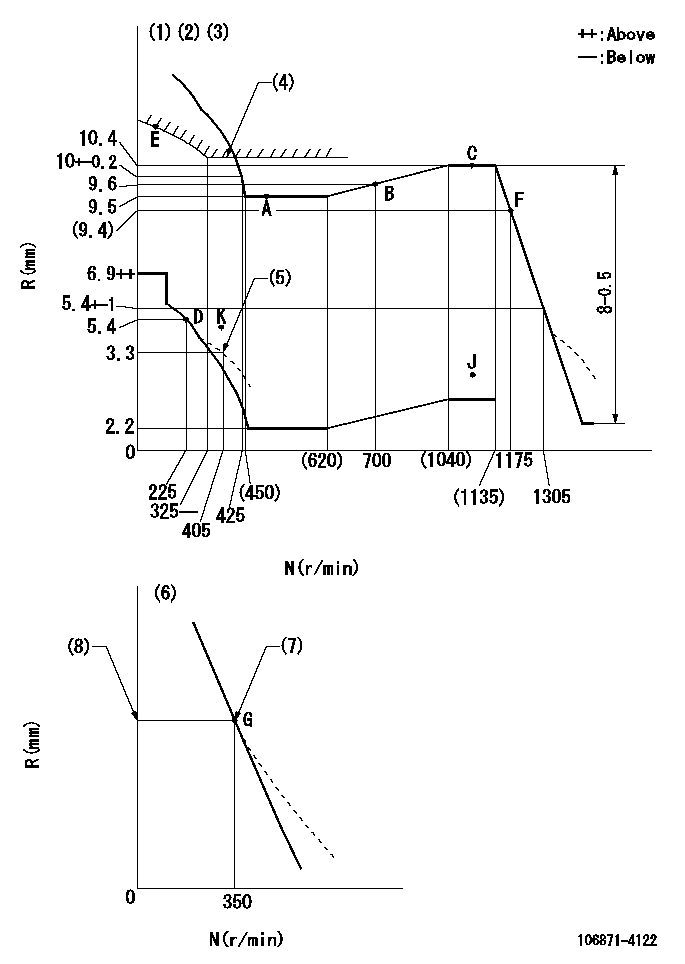
N:Pump speed
R:Rack position (mm)
(1)Lever ratio: RT
(2)Target shim dimension: TH
(3)Tolerance for racks not indicated: +-0.05mm.
(4)Excess fuel setting for starting: SXL (N = N1)
(5)Damper spring setting
(6)Variable speed specification: idling adjustment
(7)Main spring setting
(8)Rack position = actual measurement
----------
RT=0.8 TH=2.1mm SXL=10.5+0.2mm N1=350r/min
----------
----------
RT=0.8 TH=2.1mm SXL=10.5+0.2mm N1=350r/min
----------
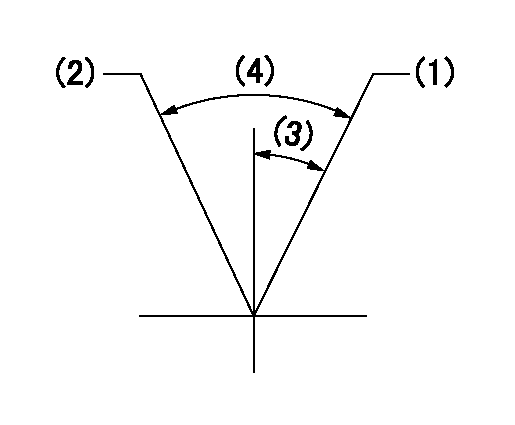
Speed control lever angle
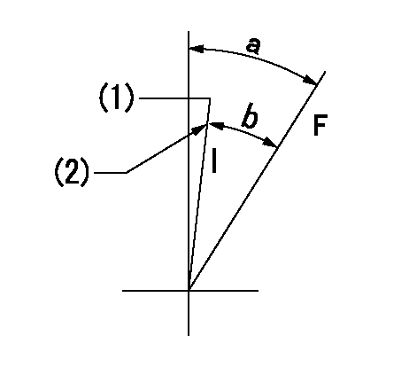
F:Full speed
I:Idle
(1)Pump speed = aa
(2)Stopper bolt setting
----------
aa=350r/min
----------
a=(20.5deg)+-5deg b=(15deg)+-5deg
----------
aa=350r/min
----------
a=(20.5deg)+-5deg b=(15deg)+-5deg
0000000901

F:Full load
I:Idle
(1)Use the hole at R = aa
(2)Stopper bolt setting
----------
aa=42mm
----------
a=39deg+-5deg b=39deg+-3deg
----------
aa=42mm
----------
a=39deg+-5deg b=39deg+-3deg
Stop lever angle
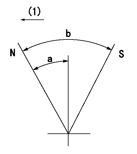
N:Pump normal
S:Stop the pump.
(1)Drive side
----------
----------
a=30deg+-5deg b=64deg+-5deg
----------
----------
a=30deg+-5deg b=64deg+-5deg
0000001201
(1)Minimum - maximum speed specification
(2)Variable speed specification
(3)(Actual measurement)
(4)(Actual measurement)
----------
----------
----------
----------
0000001501 LEVER

2-stage changeover lever adjustment
(A) Speed lever
(B) Load lever
(C) 2-stage changeover lever
(D) Link
(E) Bolt
(G) Variable speed specifications
(H) Minimum maximum speed specifications
F:Full speed
I:Idle
1. Minimum-maximum speed specification adjustment (when running)
(1)After completing governor adjustment, hold the 2-stage changeover lever (C) so that the speed lever (A) contacts the full speed stopper.
(2)In this condition, the load lever is held in the idle position.
(3)Adjust bolt (E) so that the clearance between the pin underneath lever (C) and the end of the long groove in link (D) is L.
(4)Lock using the nut.
2. Variable speed specification adjustment (at operation)
(1)Hold the 2-stage changeover lever (C) so that the load lever (B) contacts the full load stopper. (When the load lever is equipped with a cancel mechanism, move it so that it contacts the stopper without canceling.)
(2)In this condition, confirm that the speed lever (A) moves from idle to full speed.
----------
L=1~2mm
----------
----------
L=1~2mm
----------
Timing setting

(1)Pump vertical direction
(2)Coupling's key groove position at No 1 cylinder's beginning of injection
(3)B.T.D.C.: aa
(4)-
----------
aa=17.5deg
----------
a=(80deg)
----------
aa=17.5deg
----------
a=(80deg)
Information:
JANUARY 2010
INFORMATION RELEASE MEMO
Reman
PELJ1131 ?2010 Caterpillar CAT REMAN ANNOUNCES ADDITIONAL INJECTORS AND FUEL NOZZLES FOR CERTAIN C9, 3306, AND 3306B ENGINE MODELS
Announcement
Cat Reman announces the introduction of additional remanufactured injectors and nozzles. These injectors and nozzles will provide dealers and customers with additional replacement and repair options. Refer to the following table for part number details.
Availability
The above injectors and nozzles are currently available for ordering. Some of these Reman Injectors and Nozzles may be on initial seed support. For parts on initial seed support Antares may show "0" on-hand quantity for the Reman part number, however, orders for Reman will be filled with the new part equivalent. When Reman is the preferred option always order under the Reman part number regardless of what the system shows for on-hand. As long as the new equivalent part number has on-hand available the Reman order will be filled. For more details on the Reman seed policy please refer to the "Reman Parts Availability & Seeding Policy" information release memo, PELJ0816-01.
Features and Benefits
Cat? Reman Injectors and Nozzles offer excellent value to customers. Customers who want fast repair turn-around, superior quality and reliability, and lower repair costs will benefit from the use of these remanufactured air starters. Cat Reman Injectors and Nozzles provide immediate, off-the-shelf availability at a fraction of the new price.
Features Benefits
All critical engineering changes and updates included Improved reliability and performance
Worldwide availability through Cat? parts distribution system Customer access regardless of location
Backed by Cat parts warranty Consistent support
Core Acceptance
Core Acceptance Criteria for Caterpillar Remanufactured Injectors and Nozzles is simple, visual, and requires no special tools. Consult the Unit Injectors ? Electronic Core Acceptance Criteria SELD0226 or Fuel Nozzles ? Direct Injection Core Acceptance Criteria SELD0024 for complete details.
Warranty
Please consult the appropriate Cat parts warranty statement for your area.
Core Management
Please refer to the Cat Core Management Information System (CMIS 2) Parts Information application describing all Cat Reman part/CAF and related information. Also refer to other CMIS 2 inquiry applications such as Customer Profiles, Inspection Reason Codes, Inspection Line Inquiry, Add Charge Information, Entitlement Activity, Entitlement Inquiry, CCR Inquiry, CCR Entry, Shipment Processing; Process Packaging Grief; and Reporting to properly manage core returns and monitor inspection performance. This information will be available to all dealers worldwide after your CMIS 2 conversion date. In the meantime, please continue to use the current CMIS Entitlement Parts Inquiry Screen describing the list of parts in a Core Acceptability Family (CAF) and related part number detail.
For the latest updates of Reman Policies and Core Management (SELD0122), Core Management Systems & Operations Procedures (SELD0040), and Shipping Instructions (SELD0039), go to the Reman Dealer website https://catreman.cat.com. If you have any questions regarding core return processing, feel free to call Corinth toll free at (800) 537-2928. Outside the US please refer to