Information injection-pump assembly
ZEXEL
106871-3952
1068713952
HINO
220004672A
220004672a
Rating:
Cross reference number
ZEXEL
106871-3952
1068713952
HINO
220004672A
220004672a
Zexel num
Bosch num
Firm num
Name
Calibration Data:
Adjustment conditions
Test oil
1404 Test oil ISO4113 or {SAEJ967d}
1404 Test oil ISO4113 or {SAEJ967d}
Test oil temperature
degC
40
40
45
Nozzle and nozzle holder
105780-8140
Bosch type code
EF8511/9A
Nozzle
105780-0000
Bosch type code
DN12SD12T
Nozzle holder
105780-2080
Bosch type code
EF8511/9
Opening pressure
MPa
17.2
Opening pressure
kgf/cm2
175
Injection pipe
Outer diameter - inner diameter - length (mm) mm 8-3-600
Outer diameter - inner diameter - length (mm) mm 8-3-600
Overflow valve
134424-0820
Overflow valve opening pressure
kPa
127
107
147
Overflow valve opening pressure
kgf/cm2
1.3
1.1
1.5
Tester oil delivery pressure
kPa
157
157
157
Tester oil delivery pressure
kgf/cm2
1.6
1.6
1.6
Direction of rotation (viewed from drive side)
Right R
Right R
Injection timing adjustment
Direction of rotation (viewed from drive side)
Right R
Right R
Injection order
1-8-6-2-
7-5-4-3
Pre-stroke
mm
4.8
4.74
4.8
Beginning of injection position
Drive side NO.1
Drive side NO.1
Difference between angles 1
Cal 1-8 deg. 45 44.75 45.25
Cal 1-8 deg. 45 44.75 45.25
Difference between angles 2
Cal 1-6 deg. 90 89.75 90.25
Cal 1-6 deg. 90 89.75 90.25
Difference between angles 3
Cyl.1-2 deg. 135 134.75 135.25
Cyl.1-2 deg. 135 134.75 135.25
Difference between angles 4
Cal 1-7 deg. 180 179.75 180.25
Cal 1-7 deg. 180 179.75 180.25
Difference between angles 5
Cal 1-5 deg. 225 224.75 225.25
Cal 1-5 deg. 225 224.75 225.25
Difference between angles 6
Cal 1-4 deg. 270 269.75 270.25
Cal 1-4 deg. 270 269.75 270.25
Difference between angles 7
Cal 1-3 deg. 315 314.75 315.25
Cal 1-3 deg. 315 314.75 315.25
Injection quantity adjustment
Adjusting point
A
Rack position
8.5
Pump speed
r/min
700
700
700
Average injection quantity
mm3/st.
162
160
164
Max. variation between cylinders
%
0
-2
2
Basic
*
Fixing the lever
*
Boost pressure
kPa
25.3
25.3
Boost pressure
mmHg
190
190
Injection quantity adjustment_02
Adjusting point
C
Rack position
8.7
Pump speed
r/min
1100
1100
1100
Average injection quantity
mm3/st.
175
169
181
Max. variation between cylinders
%
0
-4
4
Fixing the lever
*
Boost pressure
kPa
25.3
25.3
Boost pressure
mmHg
190
190
Injection quantity adjustment_03
Adjusting point
E
Rack position
7.5
Pump speed
r/min
400
400
400
Average injection quantity
mm3/st.
127.5
125.5
129.5
Fixing the lever
*
Boost pressure
kPa
0
0
0
Boost pressure
mmHg
0
0
0
Injection quantity adjustment_04
Adjusting point
F
Rack position
-
Pump speed
r/min
100
100
100
Average injection quantity
mm3/st.
121
121
Fixing the lever
*
Boost pressure
kPa
0
0
0
Boost pressure
mmHg
0
0
0
Injection quantity adjustment_05
Adjusting point
G
Rack position
4.5+-0.5
Pump speed
r/min
225
225
225
Average injection quantity
mm3/st.
8.8
5.8
11.8
Max. variation between cylinders
%
0
-15
15
Fixing the rack
*
Boost pressure
kPa
0
0
0
Boost pressure
mmHg
0
0
0
Injection quantity adjustment_06
Adjusting point
H
Rack position
-
Pump speed
r/min
300
300
300
Average injection quantity
mm3/st.
180
177
183
Fixing the lever
*
Boost pressure
kPa
25.3
25.3
Boost pressure
mmHg
190
190
Rack limit
*
Boost compensator adjustment
Pump speed
r/min
500
500
500
Rack position
7.5
Boost pressure
kPa
4
1.3
6.7
Boost pressure
mmHg
30
10
50
Boost compensator adjustment_02
Pump speed
r/min
500
500
500
Rack position
8.1
Boost pressure
kPa
12
12
12
Boost pressure
mmHg
90
90
90
Test data Ex:
Governor adjustment
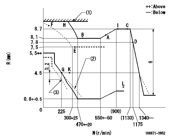
N:Pump speed
R:Rack position (mm)
(1)RACK LIMIT
(2)Damper spring setting: DL
(3)Set idle at delivery
----------
DL=2.9-0.2mm
----------
----------
DL=2.9-0.2mm
----------
Timer adjustment
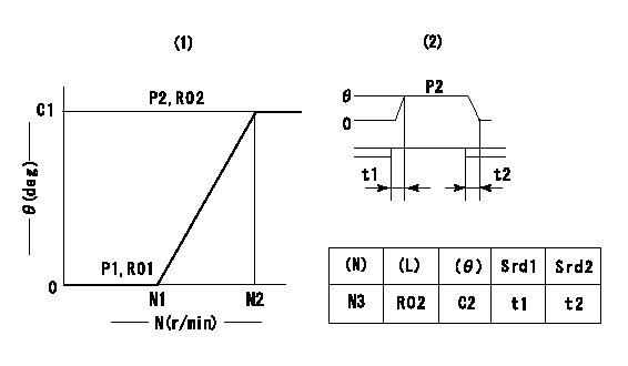
(1)Adjusting range
(2)Step response time
(N): Speed of the pump
(L): Load
(theta) Advance angle
(Srd1) Step response time 1
(Srd2) Step response time 2
1. Adjusting conditions for the variable timer
(1)Adjust the clearance between the pickup and the protrusion to L.
----------
L=1-0.2(mm) N3=800r/min C2=(7)deg t1=2-- sec. t2=2-- sec.
----------
N1=950+-50r/min N2=1500r/min P1=0 kPa(0kgf/cm2) P2=392kPa(4kgf/cm2) C1=7+-0.3deg R01=0/4 load R02=4/4 load
----------
L=1-0.2(mm) N3=800r/min C2=(7)deg t1=2-- sec. t2=2-- sec.
----------
N1=950+-50r/min N2=1500r/min P1=0 kPa(0kgf/cm2) P2=392kPa(4kgf/cm2) C1=7+-0.3deg R01=0/4 load R02=4/4 load
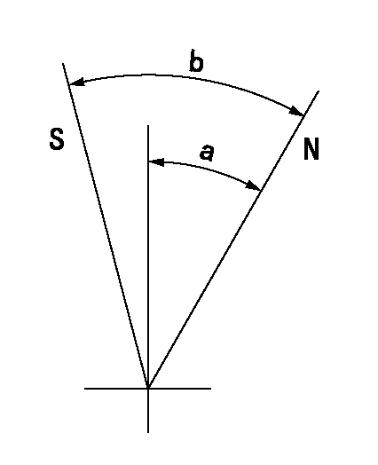
Speed control lever angle

F:Full speed
----------
----------
a=17deg+-5deg
----------
----------
a=17deg+-5deg
0000000901
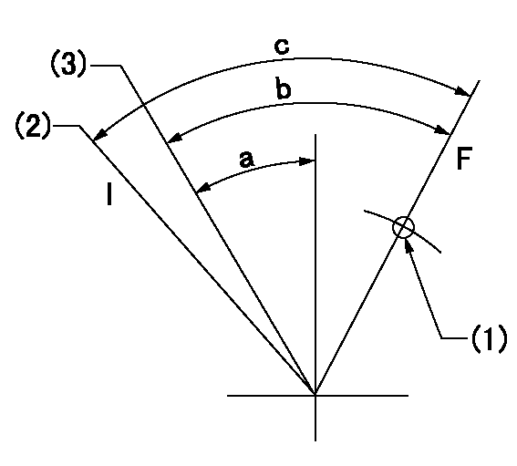
F:Full load
I:Idle
(1)Use the hole at R = aa
(2)At delivery
(3)Point G setting
----------
aa=46mm
----------
a=20deg+-5deg b=36deg+-3deg c=37deg+-5deg
----------
aa=46mm
----------
a=20deg+-5deg b=36deg+-3deg c=37deg+-5deg
Stop lever angle
N:Pump normal
S:Stop the pump.
----------
----------
a=39deg+-5deg b=48.5deg+-5deg
----------
----------
a=39deg+-5deg b=48.5deg+-5deg
0000001501 RACK SENSOR

(VR) measurement voltage
(I) Part number of the control unit
(G) Apply red paint.
(H): End surface of the pump
1. Rack limit adjustment
(1)Mount the joint (B).
(2)Select the shim (D) so that the rack limit's rack position is obtained at that time.
(3)Install the rod (E) to the block (C).
The distance between the pump end face and the rod (E) at rack limit must be L.
2. Rack sensor adjustment (-0020)
(1)Screw in the bobbin (A) until it contacts the joint (B).
(2)Fix the speed control lever at the full side.
(3)Set at speed N.
(4)Adjust the depth that the bobbin (A) is screwed in so that the control unit's rack sensor output voltage is VR+-0.01 (V), then tighten the nut (F). (If equipped with a boost compensator, perform with boost pressure applied.)
(5)Adjust the bobbin (A) so that the rack sensor's output voltage is VR+-0.01.
(6)Apply G at two places.
Connecting part between the joint (B) and the nut (F)
Connecting part between the joint (B) and the end surface of the pump (H)
----------
L=38-0.2mm N=950r/min Ra=(8.7)mm
----------
----------
L=38-0.2mm N=950r/min Ra=(8.7)mm
----------
Timing setting

(1)Pump vertical direction
(2)Coupling's key groove position at No 1 cylinder's beginning of injection
(3)-
(4)-
----------
----------
a=(90deg)
----------
----------
a=(90deg)
Information:
REM02-13
Reman
May 2002 RELOCATION OF SERVICE CENTER FOR 3600 FUEL INJECTORS Announcement Caterpillar is pleased to announce the relocation of the 3600 Fuel Injector Service Center from Booneville, MS to Caterpillar?s Fuel Injector Remanufacturing facility located in Nuevo Laredo, Mexico effective June 01, 2002. This Service Center provides a 3600 Fuel Injector ?Repair and Return? service, principally for dealers in North and South America. This move will in no way effect the excellent service Dealers have come to expect from this program. Injectors in transit to the Boonville, MS facility will be redirected to the Nuevo Laredo facility.Program Dealers can continue to send their 3600 injectors, tagged with Caterpillar? form number 00040279-00 directly to the new address listed below. New forms are being printed with a corrected ship to address. In the interim, Dealers should continue to use the old form. The Dealer will continue to be responsible for freight and insurance to and from the Service Center. The Center will, as in the past, service the injectors and return them, along with an individual certificate of conformity, to wherever the dealer requires. A database with key information on each injector will continue be maintained at the Service Center.The injectors will receive an initial inspection within five days of receipt. Normal turnaround time for the repaired injectors will be 20 ? 30 days. However, should the injectors be required urgently, this can be specified as a special instruction on the shipping tag and accommodated with a premium charge. Special return shipping instructions, such as airfreight, should also be communicated on the shipping tag. If not specified, the repaired injectors will be returned via standard surface freight to the dealer?s main office address.Shipping Location
Caterpillar Inc.
C/O Tecmosa/Dicex International
1101 Black Diamond
International Commerce Center
Laredo, TX 78045
Attn: 3600 Injector Service Center
The new Service Center Customer Service telephone number is: 1877-536-5460.
Features And BenefitsThe service provided will be a ?repair and return? service of the customer?s serialized injector, as opposed to a Reman exchange for a customer?s core. The customer will get his own injector back. It will have been completely disassembled with each component inspected, and after re-assembly, 100% tested against new specifications. A technical report will be completed and returned with each injector to help the dealer analyze any fuel system related problems, which if corrected could possibly help extend the life of the injectors.This service does not replace the remanufactured injector program. It complements it as another repair option offered at a price comparable to the competition. The dealer may choose to have the injectors cleaned or repaired. Or, depending on the need, a remanufactured injector can still be purchased. In this case the Service Center will notify the dealer and transfer the core to Reman, establishing a core credit for the dealer. This Service Center will provide one more way to lower the customer?s owning and operating expenses.Price A flat labor charge of $200 US plus any new components replaced will be