Information injection-pump assembly
ZEXEL
106871-3940
1068713940
HINO
220005071A
220005071a

Rating:
Cross reference number
ZEXEL
106871-3940
1068713940
HINO
220005071A
220005071a
Zexel num
Bosch num
Firm num
Name
Calibration Data:
Adjustment conditions
Test oil
1404 Test oil ISO4113 or {SAEJ967d}
1404 Test oil ISO4113 or {SAEJ967d}
Test oil temperature
degC
40
40
45
Nozzle and nozzle holder
105780-8140
Bosch type code
EF8511/9A
Nozzle
105780-0000
Bosch type code
DN12SD12T
Nozzle holder
105780-2080
Bosch type code
EF8511/9
Opening pressure
MPa
17.2
Opening pressure
kgf/cm2
175
Injection pipe
Outer diameter - inner diameter - length (mm) mm 8-3-600
Outer diameter - inner diameter - length (mm) mm 8-3-600
Overflow valve
134424-0820
Overflow valve opening pressure
kPa
127
107
147
Overflow valve opening pressure
kgf/cm2
1.3
1.1
1.5
Tester oil delivery pressure
kPa
157
157
157
Tester oil delivery pressure
kgf/cm2
1.6
1.6
1.6
Direction of rotation (viewed from drive side)
Right R
Right R
Injection timing adjustment
Direction of rotation (viewed from drive side)
Right R
Right R
Injection order
1-8-6-2-
7-5-4-3
Pre-stroke
mm
4.8
4.74
4.8
Beginning of injection position
Drive side NO.1
Drive side NO.1
Difference between angles 1
Cal 1-8 deg. 45 44.75 45.25
Cal 1-8 deg. 45 44.75 45.25
Difference between angles 2
Cal 1-6 deg. 90 89.75 90.25
Cal 1-6 deg. 90 89.75 90.25
Difference between angles 3
Cyl.1-2 deg. 135 134.75 135.25
Cyl.1-2 deg. 135 134.75 135.25
Difference between angles 4
Cal 1-7 deg. 180 179.75 180.25
Cal 1-7 deg. 180 179.75 180.25
Difference between angles 5
Cal 1-5 deg. 225 224.75 225.25
Cal 1-5 deg. 225 224.75 225.25
Difference between angles 6
Cal 1-4 deg. 270 269.75 270.25
Cal 1-4 deg. 270 269.75 270.25
Difference between angles 7
Cal 1-3 deg. 315 314.75 315.25
Cal 1-3 deg. 315 314.75 315.25
Injection quantity adjustment
Adjusting point
A
Rack position
8.5
Pump speed
r/min
700
700
700
Average injection quantity
mm3/st.
162
160
164
Max. variation between cylinders
%
0
-2
2
Basic
*
Fixing the lever
*
Boost pressure
kPa
25.3
25.3
Boost pressure
mmHg
190
190
Injection quantity adjustment_02
Adjusting point
C
Rack position
8.7
Pump speed
r/min
1100
1100
1100
Average injection quantity
mm3/st.
175
169
181
Max. variation between cylinders
%
0
-4
4
Fixing the lever
*
Boost pressure
kPa
25.3
25.3
Boost pressure
mmHg
190
190
Injection quantity adjustment_03
Adjusting point
E
Rack position
7.5
Pump speed
r/min
400
400
400
Average injection quantity
mm3/st.
127.5
125.5
129.5
Fixing the lever
*
Boost pressure
kPa
0
0
0
Boost pressure
mmHg
0
0
0
Injection quantity adjustment_04
Adjusting point
F
Rack position
-
Pump speed
r/min
100
100
100
Average injection quantity
mm3/st.
121
121
Fixing the lever
*
Boost pressure
kPa
0
0
0
Boost pressure
mmHg
0
0
0
Injection quantity adjustment_05
Adjusting point
G
Rack position
4.5+-0.5
Pump speed
r/min
225
225
225
Average injection quantity
mm3/st.
8.8
5.8
11.8
Max. variation between cylinders
%
0
-15
15
Fixing the rack
*
Boost pressure
kPa
0
0
0
Boost pressure
mmHg
0
0
0
Injection quantity adjustment_06
Adjusting point
H
Rack position
-
Pump speed
r/min
300
300
300
Average injection quantity
mm3/st.
180
177
183
Fixing the lever
*
Boost pressure
kPa
25.3
25.3
Boost pressure
mmHg
190
190
Rack limit
*
Boost compensator adjustment
Pump speed
r/min
500
500
500
Rack position
7.5
Boost pressure
kPa
4
1.3
6.7
Boost pressure
mmHg
30
10
50
Boost compensator adjustment_02
Pump speed
r/min
500
500
500
Rack position
8.1
Boost pressure
kPa
12
12
12
Boost pressure
mmHg
90
90
90
Test data Ex:
Governor adjustment
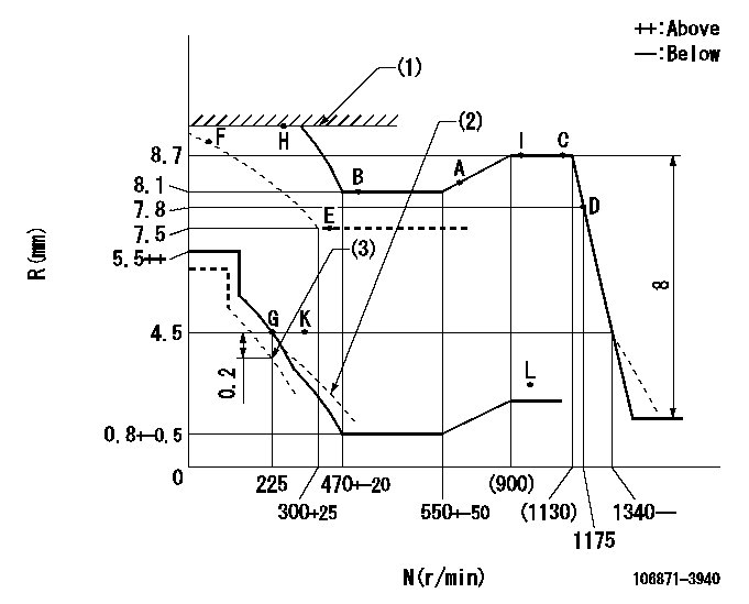
N:Pump speed
R:Rack position (mm)
(1)RACK LIMIT
(2)Damper spring setting: DL
(3)Set idle at delivery
----------
DL=2.9-0.2mm
----------
----------
DL=2.9-0.2mm
----------
Timer adjustment

(1)Adjusting range
(2)Step response time
(N): Speed of the pump
(L): Load
(theta) Advance angle
(Srd1) Step response time 1
(Srd2) Step response time 2
1. Adjusting conditions for the variable timer
(1)Adjust the clearance between the pickup and the protrusion to L.
----------
L=1-0.2mm N2=800r/min C2=(7)deg t1=2--sec. t2=2--sec.
----------
N1=950++r/min P1=0kPa(0kgf/cm2) P2=392kPa(4kgf/cm2) C1=7+-0.3deg R01=0/4load R02=4/4load
----------
L=1-0.2mm N2=800r/min C2=(7)deg t1=2--sec. t2=2--sec.
----------
N1=950++r/min P1=0kPa(0kgf/cm2) P2=392kPa(4kgf/cm2) C1=7+-0.3deg R01=0/4load R02=4/4load
Speed control lever angle

F:Full speed
----------
----------
a=17deg+-5deg
----------
----------
a=17deg+-5deg
0000000901
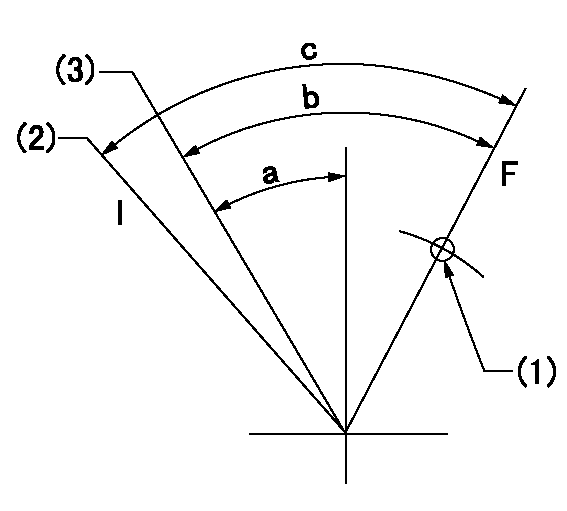
F:Full load
I:Idle
(1)Use the hole at R = aa
(2)At delivery
(3)Point G setting
----------
aa=46mm
----------
a=20deg+-5deg b=36deg+-3deg c=37deg+-5deg
----------
aa=46mm
----------
a=20deg+-5deg b=36deg+-3deg c=37deg+-5deg
Stop lever angle
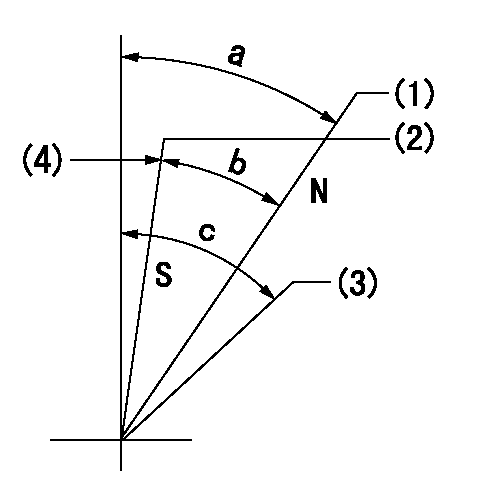
N:Engine manufacturer's normal use
S:Stop the pump.
(1)Rack position = aa
(2)Rack position bb
(3)Free (at delivery)
(4)Stopper bolt setting
----------
aa=11mm bb=2.5-0.5mm
----------
a=24deg+-5deg b=24deg+-5deg c=(40deg)
----------
aa=11mm bb=2.5-0.5mm
----------
a=24deg+-5deg b=24deg+-5deg c=(40deg)
0000001501 RACK SENSOR

(VR) measurement voltage
(I) Part number of the control unit
(G) Apply red paint.
(H): End surface of the pump
1. Rack limit adjustment
(1)Mount the joint (B).
(2)Select the shim (D) so that the rack limit's rack position is obtained at that time.
(3)Install the rod (E) to the block (C).
The distance between the pump end face and the rod (E) at rack limit must be L.
2. Rack sensor adjustment (-0020)
(1)Screw in the bobbin (A) until it contacts the joint (B).
(2)Fix the speed control lever at the full side.
(3)Set at speed N.
(4)Adjust the depth that the bobbin (A) is screwed in so that the control unit's rack sensor output voltage is VR+-0.01 (V), then tighten the nut (F). (If equipped with a boost compensator, perform with boost pressure applied.)
(5)Adjust the bobbin (A) so that the rack sensor's output voltage is VR+-0.01.
(6)Apply G at two places.
Connecting part between the joint (B) and the nut (F)
Connecting part between the joint (B) and the end surface of the pump (H)
----------
L=38-0.2mm N=950r/min Ra=(8.7)mm
----------
----------
L=38-0.2mm N=950r/min Ra=(8.7)mm
----------
Timing setting

(1)Pump vertical direction
(2)Coupling's key groove position at No 1 cylinder's beginning of injection
(3)-
(4)-
----------
----------
a=(80deg)
----------
----------
a=(80deg)
Information:
Operations that may cause product damage are identified by notice labels in this publication.
Introduction
This Tool Operating Manual contains two filter installation procedures. This first procedure is for installing a primary filter system. This is a coarse filter and will protect the transfer pump from contamination in the oil. The second procedure outlines installing a secondary filter which is designed to protect injection pumps from contaminated oil. Fuel injection pumps used on the 3208 Engine are one example of a fuel injection pump that requires the secondary filter installation.It will be the dealer choice as to which optional filter is installed on the test stand. Determine what type of filtering will be required most often, and install the appropriate type of filtering system. These filters can only be added to the 15 horsepower test stands.Secondary Filter
Nomenclature
Illustration 1. Nomenclature for Secondary Filter Installation. Refer to Chart A for item identification. Fabricated Parts
All the parts required for this installation can be ordered from Caterpillar Parts Distribution, except bracket (1). This must be manufactured by the bench owner, using the dimensions provided below.This bracket can be made from common SAE1018 steel. Weld the two pieces together.
Illustration 2. Filter Mounting Bracket. Refer to Chart B for dimensions. Installation
Assemble the Fuel Filter
1. Install 053-0088 Fitting (17) with 3J-1907 Seal (18) into the inlet port (left side) of the filter base. (This converts a number 6 STOP port to NPT). Install 5P-4455 Fitting (19) into fitting (17).2. Install 2R-6806 Fitting (15) with 3J-1907 Seal (16) into the outlet port (right side) of the filter base.3. Install 6N-4414 Cover (7) onto the filter base using 1P-0436 Gasket (8), 4B-3388/6V-2317 (9), and OS-1616/6V-8490 Bolt (10).4. Install 9S-4182 Plug (5) with 6V-5084 O-ring Seal (6) into the top of the filter base.5. Install the filter base assembly onto filter bracket (1),