Information injection-pump assembly
ZEXEL
106871-3930
1068713930
HINO
220005061A
220005061a
Rating:
Cross reference number
ZEXEL
106871-3930
1068713930
HINO
220005061A
220005061a
Zexel num
Bosch num
Firm num
Name
Calibration Data:
Adjustment conditions
Test oil
1404 Test oil ISO4113 or {SAEJ967d}
1404 Test oil ISO4113 or {SAEJ967d}
Test oil temperature
degC
40
40
45
Nozzle and nozzle holder
105780-8140
Bosch type code
EF8511/9A
Nozzle
105780-0000
Bosch type code
DN12SD12T
Nozzle holder
105780-2080
Bosch type code
EF8511/9
Opening pressure
MPa
17.2
Opening pressure
kgf/cm2
175
Injection pipe
Outer diameter - inner diameter - length (mm) mm 8-3-600
Outer diameter - inner diameter - length (mm) mm 8-3-600
Overflow valve
134424-0820
Overflow valve opening pressure
kPa
127
107
147
Overflow valve opening pressure
kgf/cm2
1.3
1.1
1.5
Tester oil delivery pressure
kPa
157
157
157
Tester oil delivery pressure
kgf/cm2
1.6
1.6
1.6
Direction of rotation (viewed from drive side)
Right R
Right R
Injection timing adjustment
Direction of rotation (viewed from drive side)
Right R
Right R
Injection order
1-8-6-2-
7-5-4-3
Pre-stroke
mm
4.8
4.74
4.8
Beginning of injection position
Drive side NO.1
Drive side NO.1
Difference between angles 1
Cal 1-8 deg. 45 44.75 45.25
Cal 1-8 deg. 45 44.75 45.25
Difference between angles 2
Cal 1-6 deg. 90 89.75 90.25
Cal 1-6 deg. 90 89.75 90.25
Difference between angles 3
Cyl.1-2 deg. 135 134.75 135.25
Cyl.1-2 deg. 135 134.75 135.25
Difference between angles 4
Cal 1-7 deg. 180 179.75 180.25
Cal 1-7 deg. 180 179.75 180.25
Difference between angles 5
Cal 1-5 deg. 225 224.75 225.25
Cal 1-5 deg. 225 224.75 225.25
Difference between angles 6
Cal 1-4 deg. 270 269.75 270.25
Cal 1-4 deg. 270 269.75 270.25
Difference between angles 7
Cal 1-3 deg. 315 314.75 315.25
Cal 1-3 deg. 315 314.75 315.25
Injection quantity adjustment
Adjusting point
A
Rack position
8.5
Pump speed
r/min
700
700
700
Average injection quantity
mm3/st.
162
160
164
Max. variation between cylinders
%
0
-2
2
Basic
*
Fixing the lever
*
Boost pressure
kPa
25.3
25.3
Boost pressure
mmHg
190
190
Injection quantity adjustment_02
Adjusting point
C
Rack position
8.7
Pump speed
r/min
1100
1100
1100
Average injection quantity
mm3/st.
175
169
181
Max. variation between cylinders
%
0
-4
4
Fixing the lever
*
Boost pressure
kPa
25.3
25.3
Boost pressure
mmHg
190
190
Injection quantity adjustment_03
Adjusting point
E
Rack position
7.5
Pump speed
r/min
400
400
400
Average injection quantity
mm3/st.
127.5
125.5
129.5
Fixing the lever
*
Boost pressure
kPa
0
0
0
Boost pressure
mmHg
0
0
0
Injection quantity adjustment_04
Adjusting point
F
Rack position
-
Pump speed
r/min
100
100
100
Average injection quantity
mm3/st.
121
121
Fixing the lever
*
Boost pressure
kPa
0
0
0
Boost pressure
mmHg
0
0
0
Injection quantity adjustment_05
Adjusting point
G
Rack position
4.5+-0.5
Pump speed
r/min
225
225
225
Average injection quantity
mm3/st.
8.8
5.8
11.8
Max. variation between cylinders
%
0
-15
15
Fixing the rack
*
Boost pressure
kPa
0
0
0
Boost pressure
mmHg
0
0
0
Injection quantity adjustment_06
Adjusting point
H
Rack position
-
Pump speed
r/min
300
300
300
Average injection quantity
mm3/st.
180
177
183
Fixing the lever
*
Boost pressure
kPa
25.3
25.3
Boost pressure
mmHg
190
190
Rack limit
*
Boost compensator adjustment
Pump speed
r/min
500
500
500
Rack position
7.5
Boost pressure
kPa
4
1.3
6.7
Boost pressure
mmHg
30
10
50
Boost compensator adjustment_02
Pump speed
r/min
500
500
500
Rack position
8.1
Boost pressure
kPa
12
12
12
Boost pressure
mmHg
90
90
90
Timer adjustment
Pump speed
r/min
(950)
Advance angle
deg.
0
0
0
Remarks
Start
Start
Timer adjustment_02
Pump speed
r/min
1100
Advance angle
deg.
2
1.7
2.3
Remarks
Finish
Finish
Test data Ex:
Governor adjustment
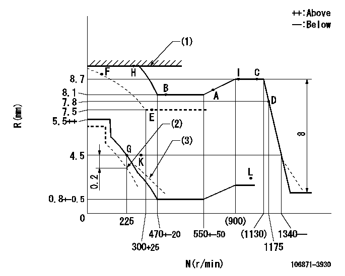
N:Pump speed
R:Rack position (mm)
(1)RACK LIMIT
(2)Set idle at delivery
(3)Damper spring setting: DL
----------
DL=2.9-0.2mm
----------
----------
DL=2.9-0.2mm
----------
Speed control lever angle

F:Full speed
----------
----------
a=17deg+-5deg
----------
----------
a=17deg+-5deg
0000000901
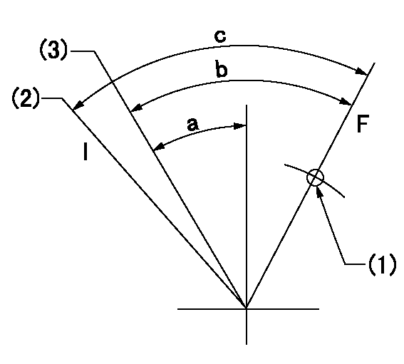
F:Full load
I:Idle
(1)Use the hole at R = aa
(2)At delivery
(3)Point G setting
----------
aa=46mm
----------
a=20deg+-5deg b=36deg+-3deg c=37deg+-5deg
----------
aa=46mm
----------
a=20deg+-5deg b=36deg+-3deg c=37deg+-5deg
Stop lever angle
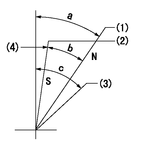
N:Engine manufacturer's normal use
S:Stop the pump.
(1)Rack position = aa
(2)Rack position bb
(3)Free (at delivery)
(4)Stopper bolt setting
----------
aa=11mm bb=2.5-0.5mm
----------
a=24deg+-5deg b=24deg+-5deg c=(40deg)
----------
aa=11mm bb=2.5-0.5mm
----------
a=24deg+-5deg b=24deg+-5deg c=(40deg)
Timing setting

(1)Pump vertical direction
(2)Coupling's key groove position at No 1 cylinder's beginning of injection
(3)-
(4)-
----------
----------
a=(80deg)
----------
----------
a=(80deg)
Information:
These recommendations are subject to change without notice. Consult your local Cat dealer for the most up to date recommendations.
Diesel engines may burn a wide variety of fuels. These fuels are divided into two general groups. The two groups are called the preferred fuels and the permissible fuels.The preferred fuels provide maximum engine service life and performance. The preferred fuels are distillate fuels. These fuels are commonly called diesel fuel, furnace oil, gas oil, or kerosene. These fuels must meet the “Cat Specification for Distillate Diesel Fuel for Off-Highway Diesel Engines” found in this Special Publication, "Distillate Diesel Fuel" article.The permissible fuels are some crude oils, some blends of crude oil with distillate fuel, and some marine diesel fuel. These fuels are not suitable for use in all engine applications. The acceptability of these fuels for use is determined on a case by case basis. A complete fuel analysis is required. Consult your Cat dealer for further information. Biodiesel fuel is permissible for use in Cat engines. Follow all the recommendations and guidelines given in this Special Publication, "Biodiesel" article.Note: Except for some biodiesel, permissible fuels are not acceptable for use in on-highway applications.
Use of permissible fuels can result in higher maintenance costs and reduced engine service life.
Note: Use of fuels that do not meet at least the minimum performance recommendations and/or requirements may lead to lower compartment performance and/or compartment failure. Problems/failures that are caused by using fuels that do not meet the minimum recommended and/or required performance level are not Cat factory defects and therefore are NOT covered by the Cat warranty. The fuel supplier and customer are responsible.