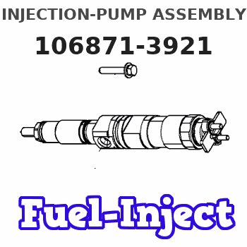
Information injection-pump assembly
ZEXEL
106871-3921
1068713921
HINO
220005141A
220005141a
Rating:
Cross reference number
ZEXEL
106871-3921
1068713921
HINO
220005141A
220005141a
Zexel num
Bosch num
Firm num
Name
Calibration Data:
Adjustment conditions
Test oil
1404 Test oil ISO4113 or {SAEJ967d}
1404 Test oil ISO4113 or {SAEJ967d}
Test oil temperature
degC
40
40
45
Nozzle and nozzle holder
105780-8140
Bosch type code
EF8511/9A
Nozzle
105780-0000
Bosch type code
DN12SD12T
Nozzle holder
105780-2080
Bosch type code
EF8511/9
Opening pressure
MPa
17.2
Opening pressure
kgf/cm2
175
Injection pipe
Outer diameter - inner diameter - length (mm) mm 8-3-600
Outer diameter - inner diameter - length (mm) mm 8-3-600
Overflow valve
134424-0820
Overflow valve opening pressure
kPa
127
107
147
Overflow valve opening pressure
kgf/cm2
1.3
1.1
1.5
Tester oil delivery pressure
kPa
157
157
157
Tester oil delivery pressure
kgf/cm2
1.6
1.6
1.6
Direction of rotation (viewed from drive side)
Right R
Right R
Injection timing adjustment
Direction of rotation (viewed from drive side)
Right R
Right R
Injection order
1-8-6-2-
7-5-4-3
Pre-stroke
mm
4.8
4.74
4.8
Beginning of injection position
Drive side NO.1
Drive side NO.1
Difference between angles 1
Cal 1-8 deg. 45 44.75 45.25
Cal 1-8 deg. 45 44.75 45.25
Difference between angles 2
Cal 1-6 deg. 90 89.75 90.25
Cal 1-6 deg. 90 89.75 90.25
Difference between angles 3
Cyl.1-2 deg. 135 134.75 135.25
Cyl.1-2 deg. 135 134.75 135.25
Difference between angles 4
Cal 1-7 deg. 180 179.75 180.25
Cal 1-7 deg. 180 179.75 180.25
Difference between angles 5
Cal 1-5 deg. 225 224.75 225.25
Cal 1-5 deg. 225 224.75 225.25
Difference between angles 6
Cal 1-4 deg. 270 269.75 270.25
Cal 1-4 deg. 270 269.75 270.25
Difference between angles 7
Cal 1-3 deg. 315 314.75 315.25
Cal 1-3 deg. 315 314.75 315.25
Injection quantity adjustment
Adjusting point
A
Rack position
7.3
Pump speed
r/min
700
700
700
Average injection quantity
mm3/st.
112.5
110.5
114.5
Max. variation between cylinders
%
0
-2
2
Basic
*
Fixing the lever
*
Injection quantity adjustment_02
Adjusting point
B
Rack position
7.6
Pump speed
r/min
900
900
900
Average injection quantity
mm3/st.
129
126
132
Fixing the lever
*
Injection quantity adjustment_03
Adjusting point
C
Rack position
7.8
Pump speed
r/min
1100
1100
1100
Average injection quantity
mm3/st.
130.5
127.5
133.5
Max. variation between cylinders
%
0
-4
4
Fixing the lever
*
Injection quantity adjustment_04
Adjusting point
-
Rack position
5.1+-0.5
Pump speed
r/min
225
225
225
Average injection quantity
mm3/st.
12.6
9.6
15.6
Max. variation between cylinders
%
0
-15
15
Fixing the rack
*
Remarks
Adjust only variation between cylinders; adjust governor according to governor specifications.
Adjust only variation between cylinders; adjust governor according to governor specifications.
Injection quantity adjustment_05
Adjusting point
E
Rack position
7.3
Pump speed
r/min
500
500
500
Average injection quantity
mm3/st.
110
104
116
Fixing the lever
*
Injection quantity adjustment_06
Adjusting point
F
Rack position
10+-0.5
Pump speed
r/min
100
100
100
Average injection quantity
mm3/st.
140
140
150
Fixing the lever
*
Rack limit
*
Timer adjustment
Pump speed
r/min
(875)
Advance angle
deg.
0
0
0
Remarks
Start
Start
Timer adjustment_02
Pump speed
r/min
1075
Advance angle
deg.
4.75
4.45
5.05
Remarks
Finish
Finish
Test data Ex:
Governor adjustment
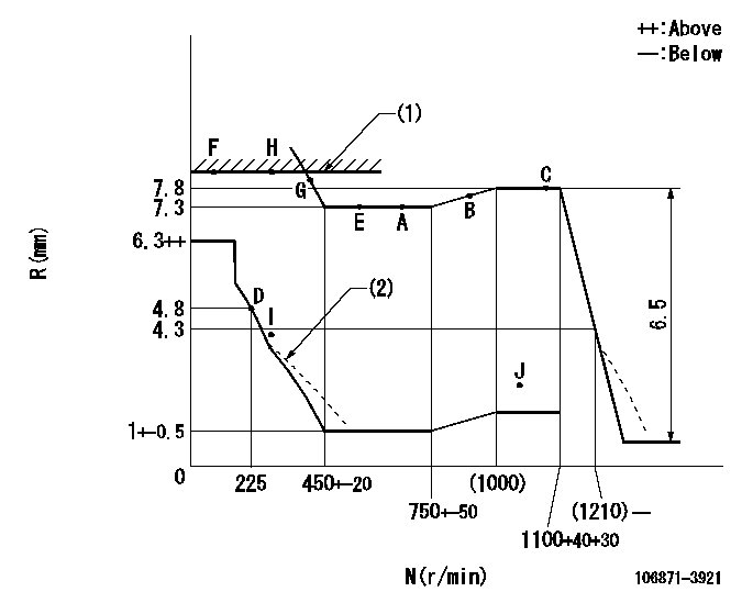
N:Pump speed
R:Rack position (mm)
(1)RACK LIMIT
(2)Damper spring setting: DL
----------
DL=3.8-0.5mm
----------
----------
DL=3.8-0.5mm
----------
Speed control lever angle

F:Full speed
----------
----------
a=19deg+-5deg
----------
----------
a=19deg+-5deg
0000000901
F:Full load
I:Idle
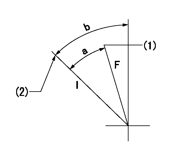
(1)Use the hole at R = aa
(2)Stopper bolt setting
----------
aa=50mm
----------
a=34deg+-3deg b=39deg+-5deg
----------
aa=50mm
----------
a=34deg+-3deg b=39deg+-5deg
Stop lever angle

N:Pump normal
S:Stop the pump.
----------
----------
a=15deg+-5deg b=64deg+-5deg
----------
----------
a=15deg+-5deg b=64deg+-5deg
Timing setting

(1)Pump vertical direction
(2)Coupling's key groove position at No 1 cylinder's beginning of injection
(3)-
(4)-
----------
----------
a=(80deg)
----------
----------
a=(80deg)
Information:
Fuel Return Manifold Leaks and/or Leaks at Fuel Return Boots or Connectors ... Remove the valve cover(s). Make a visual inspection of the fuel return manifold, fuel return boots, and connectors. Boots and/or connectors with damage, or wrongly installed, will let fuel get into the oil. If you do not see leaks during the visual inspection, start the engine and visually inspect while the engine is running. Boots and/or connectors can cause leakage if the fuel return line has a restriction.Loose Fuel Injection Nozzle Nut(s) ... A loose fuel injection nozzle nut can cause fuel leakage. Tighten nozzle nut(s) to 30 5 lb. ft. (4,1 0,7 mkg).Defective Fuel Nozzle(s) ... Check fuel nozzle(s) for cracks in inlet fitting, inlet line, or nozzle body. If you do not see a crack, start the engine and visually inspect each nozzle for leaks. Cracks in the inlet fitting and nozzle body are nozzle defects. Cracks in the inlet line are caused by the nozzle not being tightened correctly.Defective Diaphragm in Fuel Transfer Pump ... A defective diaphragm will cause fuel leakage through the orifice in the fuel transfer pump housing. If you do not see leakage, make sure the orifice is open. Start the engine and again look for possible leakage. If the pump has leaks, install a new pump.Loose Fuel Injection Pump Retaining Bushing ... Loose retaining bushings will not hold the barrel of the injection pump correctly against the seat in the pump housing and fuel can get into the crankcase. A loose bushing can cause the engine to misfire or cause fuel leakage to the outside of the pump housing. Remove the fuel lines at the fuel injection pump and tighten each retaining bushing to 100 10 lb. ft. (13,8 1,4 mkg). To tighten the three rear retaining bushings the pump housing must be removed from the engine.Fuel Leaks Between Injection Pump Barrel(s) and Injection Pump Housing ... Dirt or foreign material under the barrel of the fuel injection pump will cause fuel leakage into the crankcase. Remove the housing of the fuel injection pump and the governor from the engine. Remove the plunger and barrel assemblies from the pump housing. Inspect the seat area of the barrel and housing. Be sure the seat is smooth and flat. Check the timing dimension and adjust as necessary. Install the fuel injection pumps. *Worn Fuel Injection Pumps ... It is possible for one or more of the plunger and barrel assemblies to be worn enough to cause fuel leakage between the plunger and barrel. Remove the housing of the fuel injection pump and the governor from the engine. Test the fuel injection pump on the test bench for fuel injection pumps. If a test bench is not available, install new plunger and barrel assemblies in place of those with damage.*Authorized dealers are equipped with the necessary tools and personnel familiar with disassembly and assembly procedures to perform these services.