Information injection-pump assembly
ZEXEL
106871-3911
1068713911
HINO
220005001A
220005001a
Rating:
Cross reference number
ZEXEL
106871-3911
1068713911
HINO
220005001A
220005001a
Zexel num
Bosch num
Firm num
Name
Calibration Data:
Adjustment conditions
Test oil
1404 Test oil ISO4113 or {SAEJ967d}
1404 Test oil ISO4113 or {SAEJ967d}
Test oil temperature
degC
40
40
45
Nozzle and nozzle holder
105780-8140
Bosch type code
EF8511/9A
Nozzle
105780-0000
Bosch type code
DN12SD12T
Nozzle holder
105780-2080
Bosch type code
EF8511/9
Opening pressure
MPa
17.2
Opening pressure
kgf/cm2
175
Injection pipe
Outer diameter - inner diameter - length (mm) mm 8-3-600
Outer diameter - inner diameter - length (mm) mm 8-3-600
Overflow valve
134424-0820
Overflow valve opening pressure
kPa
127
107
147
Overflow valve opening pressure
kgf/cm2
1.3
1.1
1.5
Tester oil delivery pressure
kPa
157
157
157
Tester oil delivery pressure
kgf/cm2
1.6
1.6
1.6
Direction of rotation (viewed from drive side)
Right R
Right R
Injection timing adjustment
Direction of rotation (viewed from drive side)
Right R
Right R
Injection order
1-8-6-2-
7-5-4-3
Pre-stroke
mm
4.8
4.74
4.8
Beginning of injection position
Drive side NO.1
Drive side NO.1
Difference between angles 1
Cal 1-8 deg. 45 44.75 45.25
Cal 1-8 deg. 45 44.75 45.25
Difference between angles 2
Cal 1-6 deg. 90 89.75 90.25
Cal 1-6 deg. 90 89.75 90.25
Difference between angles 3
Cyl.1-2 deg. 135 134.75 135.25
Cyl.1-2 deg. 135 134.75 135.25
Difference between angles 4
Cal 1-7 deg. 180 179.75 180.25
Cal 1-7 deg. 180 179.75 180.25
Difference between angles 5
Cal 1-5 deg. 225 224.75 225.25
Cal 1-5 deg. 225 224.75 225.25
Difference between angles 6
Cal 1-4 deg. 270 269.75 270.25
Cal 1-4 deg. 270 269.75 270.25
Difference between angles 7
Cal 1-3 deg. 315 314.75 315.25
Cal 1-3 deg. 315 314.75 315.25
Injection quantity adjustment
Adjusting point
A
Rack position
8.5
Pump speed
r/min
700
700
700
Average injection quantity
mm3/st.
162
160
164
Max. variation between cylinders
%
0
-2
2
Basic
*
Fixing the lever
*
Boost pressure
kPa
25.3
25.3
Boost pressure
mmHg
190
190
Injection quantity adjustment_02
Adjusting point
C
Rack position
8.7
Pump speed
r/min
1100
1100
1100
Average injection quantity
mm3/st.
175
169
181
Max. variation between cylinders
%
0
-4
4
Fixing the lever
*
Boost pressure
kPa
25.3
25.3
Boost pressure
mmHg
190
190
Injection quantity adjustment_03
Adjusting point
E
Rack position
7.5
Pump speed
r/min
400
400
400
Average injection quantity
mm3/st.
127.5
125.5
129.5
Fixing the lever
*
Boost pressure
kPa
0
0
0
Boost pressure
mmHg
0
0
0
Injection quantity adjustment_04
Adjusting point
F
Rack position
-
Pump speed
r/min
100
100
100
Average injection quantity
mm3/st.
121
121
Fixing the lever
*
Boost pressure
kPa
0
0
0
Boost pressure
mmHg
0
0
0
Injection quantity adjustment_05
Adjusting point
G
Rack position
4.5+-0.5
Pump speed
r/min
225
225
225
Average injection quantity
mm3/st.
8.8
5.8
11.8
Max. variation between cylinders
%
0
-15
15
Fixing the rack
*
Boost pressure
kPa
0
0
0
Boost pressure
mmHg
0
0
0
Injection quantity adjustment_06
Adjusting point
H
Rack position
-
Pump speed
r/min
300
300
300
Average injection quantity
mm3/st.
180
177
183
Fixing the lever
*
Boost pressure
kPa
25.3
25.3
Boost pressure
mmHg
190
190
Rack limit
*
Boost compensator adjustment
Pump speed
r/min
500
500
500
Rack position
7.5
Boost pressure
kPa
4
1.3
6.7
Boost pressure
mmHg
30
10
50
Boost compensator adjustment_02
Pump speed
r/min
500
500
500
Rack position
8.1
Boost pressure
kPa
12
12
12
Boost pressure
mmHg
90
90
90
Timer adjustment
Pump speed
r/min
(950)
Advance angle
deg.
0
0
0
Remarks
Start
Start
Timer adjustment_02
Pump speed
r/min
1100
Advance angle
deg.
2
1.7
2.3
Remarks
Finish
Finish
Test data Ex:
Governor adjustment
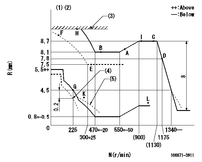
N:Pump speed
R:Rack position (mm)
(1)Lever ratio: RT
(2)Target shim dimension: TH
(3)RACK LIMIT
(4)Set idle at delivery
(5)Damper spring setting: DL
----------
RT=0.8 TH=2mm DL=2.9-0.2mm
----------
----------
RT=0.8 TH=2mm DL=2.9-0.2mm
----------
Speed control lever angle

F:Full speed
----------
----------
a=17deg+-5deg
----------
----------
a=17deg+-5deg
0000000901
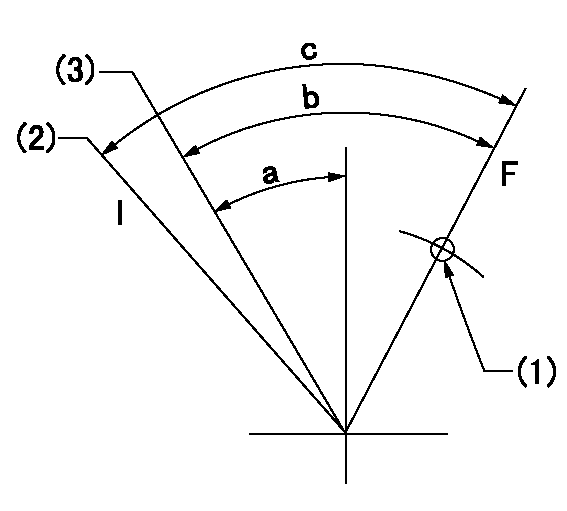
F:Full load
I:Idle
(1)Use the hole at R = aa
(2)At delivery
(3)Point G setting
----------
aa=46mm
----------
a=20deg+-5deg b=36deg+-3deg c=37deg+-5deg
----------
aa=46mm
----------
a=20deg+-5deg b=36deg+-3deg c=37deg+-5deg
Stop lever angle
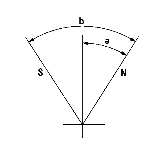
N:Pump normal
S:Stop the pump.
----------
----------
a=39deg+-5deg b=48.5deg+-5deg
----------
----------
a=39deg+-5deg b=48.5deg+-5deg
Timing setting

(1)Pump vertical direction
(2)Coupling's key groove position at No 1 cylinder's beginning of injection
(3)-
(4)-
----------
----------
a=(80deg)
----------
----------
a=(80deg)
Information:
Tachometer Error...To check, connect a tachometer of known accuracy to the engine. Run the engine and make a comparison of the readings of the vehicle and test tachometers. If vehicle tachometer is defective, make repairs as necessary or install a new tachometer.Engine Operated at High Altitude...Less oxygen at higher altitudes causes the engine horsepower to go down approximately three percent for each 1000 ft. above sea level. *Brakes Do Not Completely Release... Check the brakes by feeling all the brake drums. If the brakes do not completely release, the brake drum for that wheel will be hotter than the brake drums for the other wheels. With the truck jacked up the wheels must rotate freely when turned by hand.Vehicle Operated in Too High a Gear... If the operator does not shift the truck correctly or operates the truck in a "lug" condition (using the truck in too high a gear for engine rpm to go up as accelerator pedal is pushed farther down, or using the truck in a gear where engine rpm goes down with accelerator pedal at maximum travel), poor vehicle performance is the result. For best engine performance do not lug the engine more than 600 rpm below its full load speed.Extra Engine Driven Equipment...Air compressors, hydraulic pumps, generators, and other engine driven equipment that has damage, or that was not installed correctly, or that is not in correct adjustment, can take more horsepower to drive than expected. If necessary, disconnect the equipment and test the engine.Speedometer Error...A damaged speedometer does not give the correct speed or the correct indication of fuel consumption. An indication of low speed can cause the operator to feel that he has a power problem.Speeds Too High...The need for more horsepower is easy to see as the speed of the vehicle is increased. This is especially true if the front of the vehicle has a large surface area. Your authorized dealer can give you the horsepower needs for a vehicle, and the horsepower necessary for different vehicle designs at different speeds.Overload on Vehicle *High Moving Resistance...Soft ground conditions cause a need for more horsepower. To see if the problem is the engine, test the vehicle on a surface known to be good, or test on a chassis dynamometer.High Wind Resistance...The horsepower needs for a truck can be divided into two parts. Part of the horsepower is used to move the vehicle and part is used to get through wind resistance. The horsepower necessary to get through the wind resistance will increase as the vehicle is used at higher speeds. Vehicles with a large front area have a higher wind resistance and take more horsepower than those with a small front area. Some types of trucks, for example those used for the transportation of automobiles and/or boats have high wind resistance even if the front area is small. Moving against the wind has the same effect on wind resistance as does higher vehicle speed.Power Loss in Drive Gears...It is possible for