Information injection-pump assembly
BOSCH
9 400 618 116
9400618116
ZEXEL
106871-3821
1068713821
HINO
220004801A
220004801a

Rating:
Service parts 106871-3821 INJECTION-PUMP ASSEMBLY:
1.
_
7.
COUPLING PLATE
8.
_
9.
_
11.
Nozzle and Holder
236001530B
12.
Open Pre:MPa(Kqf/cm2)
18.1(185)
15.
NOZZLE SET
Include in #1:
106871-3821
as INJECTION-PUMP ASSEMBLY
Cross reference number
BOSCH
9 400 618 116
9400618116
ZEXEL
106871-3821
1068713821
HINO
220004801A
220004801a
Zexel num
Bosch num
Firm num
Name
106871-3821
9 400 618 116
220004801A HINO
INJECTION-PUMP ASSEMBLY
EF750 * K 14CD PE8P PE
EF750 * K 14CD PE8P PE
Calibration Data:
Adjustment conditions
Test oil
1404 Test oil ISO4113 or {SAEJ967d}
1404 Test oil ISO4113 or {SAEJ967d}
Test oil temperature
degC
40
40
45
Nozzle and nozzle holder
105780-8140
Bosch type code
EF8511/9A
Nozzle
105780-0000
Bosch type code
DN12SD12T
Nozzle holder
105780-2080
Bosch type code
EF8511/9
Opening pressure
MPa
17.2
Opening pressure
kgf/cm2
175
Injection pipe
Outer diameter - inner diameter - length (mm) mm 8-3-600
Outer diameter - inner diameter - length (mm) mm 8-3-600
Overflow valve
134424-1020
Overflow valve opening pressure
kPa
127
107
147
Overflow valve opening pressure
kgf/cm2
1.3
1.1
1.5
Tester oil delivery pressure
kPa
157
157
157
Tester oil delivery pressure
kgf/cm2
1.6
1.6
1.6
Direction of rotation (viewed from drive side)
Right R
Right R
Injection timing adjustment
Direction of rotation (viewed from drive side)
Right R
Right R
Injection order
1-8-6-2-
7-5-4-3
Pre-stroke
mm
4.4
4.34
4.4
Beginning of injection position
Drive side NO.1
Drive side NO.1
Difference between angles 1
Cal 1-8 deg. 45 44.75 45.25
Cal 1-8 deg. 45 44.75 45.25
Difference between angles 2
Cal 1-6 deg. 90 89.75 90.25
Cal 1-6 deg. 90 89.75 90.25
Difference between angles 3
Cyl.1-2 deg. 135 134.75 135.25
Cyl.1-2 deg. 135 134.75 135.25
Difference between angles 4
Cal 1-7 deg. 180 179.75 180.25
Cal 1-7 deg. 180 179.75 180.25
Difference between angles 5
Cal 1-5 deg. 225 224.75 225.25
Cal 1-5 deg. 225 224.75 225.25
Difference between angles 6
Cal 1-4 deg. 270 269.75 270.25
Cal 1-4 deg. 270 269.75 270.25
Difference between angles 7
Cal 1-3 deg. 315 314.75 315.25
Cal 1-3 deg. 315 314.75 315.25
Injection quantity adjustment
Adjusting point
A
Rack position
9.5
Pump speed
r/min
500
500
500
Average injection quantity
mm3/st.
120
117
123
Max. variation between cylinders
%
0
-4
4
Fixing the lever
*
Injection quantity adjustment_02
Adjusting point
B
Rack position
9.6
Pump speed
r/min
700
700
700
Average injection quantity
mm3/st.
121.8
119.8
123.8
Max. variation between cylinders
%
0
-2
2
Basic
*
Fixing the lever
*
Injection quantity adjustment_03
Adjusting point
C
Rack position
10.4
Pump speed
r/min
1100
1100
1100
Average injection quantity
mm3/st.
145
142
148
Max. variation between cylinders
%
0
-4
4
Fixing the lever
*
Injection quantity adjustment_04
Adjusting point
D
Rack position
5.4+-0.5
Pump speed
r/min
225
225
225
Average injection quantity
mm3/st.
11.5
8.5
14.5
Max. variation between cylinders
%
0
-15
15
Fixing the rack
*
Injection quantity adjustment_05
Adjusting point
E
Rack position
-
Pump speed
r/min
100
100
100
Average injection quantity
mm3/st.
140
140
160
Fixing the lever
*
Remarks
After startup boost setting
After startup boost setting
Timer adjustment
Pump speed
r/min
750--
Advance angle
deg.
0
0
0
Remarks
Start
Start
Timer adjustment_02
Pump speed
r/min
700
Advance angle
deg.
0.5
Timer adjustment_03
Pump speed
r/min
1100
Advance angle
deg.
3.5
3.2
3.8
Remarks
Finish
Finish
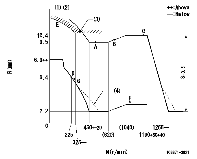
Test data Ex:
Governor adjustment

N:Pump speed
R:Rack position (mm)
(1)Lever ratio: RT
(2)Target shim dimension: TH
(3)Excess fuel setting for starting: SXL
(4)Damper spring setting: DL
----------
RT=0.8 TH=2.7mm SXL=10.4+0.2mm DL=4.4-0.2mm
----------
----------
RT=0.8 TH=2.7mm SXL=10.4+0.2mm DL=4.4-0.2mm
----------
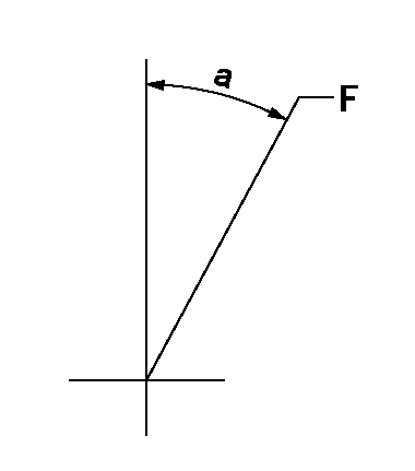
Speed control lever angle

F:Full speed
----------
----------
a=17deg+-5deg
----------
----------
a=17deg+-5deg
0000000901

F:Full load
I:Idle
(1)Stopper bolt setting
(2)Use the hole at R = aa
----------
aa=50mm
----------
a=39deg+-3deg b=39deg+-5deg
----------
aa=50mm
----------
a=39deg+-3deg b=39deg+-5deg
Stop lever angle

N:Pump normal
S:Stop the pump.
----------
----------
a=15deg+-5deg b=64deg+-5deg
----------
----------
a=15deg+-5deg b=64deg+-5deg
Timing setting

(1)Pump vertical direction
(2)Coupling's key groove position at No 1 cylinder's beginning of injection
(3)-
(4)-
----------
----------
a=(80deg)
----------
----------
a=(80deg)
Information:
This engine has an exhaust driven turbocharger to provide compacted air to the cylinders.The exhaust gases enter the turbine housing and are directed through the blades of a turbine wheel, causing the turbine wheel and a compressor wheel to rotate.Filtered inlet air from the air cleaner is drawn through the air inlet of the compressor housing by the rotating compressor wheel. The air is forced through the aftercooler to the inlet manifold of the engine and is compressed by action of the compressor impeller.When the intake air passes through and is compressed by the turbocharger, it becomes heated and becomes less dense. By directing air through the aftercooler located between the turbocharger and the inlet manifold, some of that heat is removed from the air. The aftercooler is a simple device resembling a small radiator core. Coolant from the engine passes through the core tubes and the compressed air is directed around the tubes. Since the temperature of the coolant is lower than the air, the air is cooled as it leaves the aftercooler. This means more air (oxygen) is available for combustion, resulting in more fuel being burned and more power produced.When engine load increases, more fuel is injected into the engine cylinders. The increased volume of exhaust gas causes the turbocharger turbine wheel and compressor impeller to rotate faster. The higher RPM of the impeller increases the quantity of inlet air. As the turbocharger provides additional inlet air, more fuel can be burned; hence more horsepower derived from the engine.The turbocharger is mounted to the engine exhaust manifold. All the exhaust gases from the diesel engine pass through the turbocharger.The turbocharger bearings are pressure-lubricated by engine oil. The oil enters the top of the center section and is directed through passages to lubricate the thrust bearing, sleeves and the journal bearings of the turbocharger. Oil leaves the turbocharger through a port in the bottom of the center section and is returned to the engine sump.
CROSS SECTION OF THE TURBOCHARGERMaximum turbocharger speed is determined by the rack setting, the high idle speed setting and the altitude at which the engine is operated. The high idle speed and the rack setting are not the same for all altitudes.
If the high idle speed or the rack setting is greater than specified for the altitude at which the engine is operated, damage to engine or turbocharger parts can result.
The fuel pump rack has been set by qualified personnel for a particular engine application. The governor housing and turbocharger are sealed to prevent unqualified personnel from tampering with the adjustments.The engine can be operated at a lower altitude than specified without danger of engine damage. In this situation the engine will perform at slightly less than maximum efficiency. When operated at a higher altitude, the rack setting and high idle speed setting must be changed.The principal cause of fouled valves, damaged bearings, worn piston rings and cylinder liners is the entrance of airborne foreign matter into the engine cylinders; therefore,
Have questions with 106871-3821?
Group cross 106871-3821 ZEXEL
Hino
106871-3821
9 400 618 116
220004801A
INJECTION-PUMP ASSEMBLY
EF750
EF750
